
System and method for controlling water quantity of closestool

A water volume control and toilet technology, which is applied to water supply devices, flushing equipment with water tanks, buildings, etc., can solve the problems of unclean toilet flushing, inability to accurately control toilet water consumption, and inability to ensure toilet flushing performance, etc., and achieve good flushing effect. Effect

Active Publication Date: 2015-01-07
KOHLER CHINA INVESTMENT
View PDF8 Cites 17 Cited by
  • Summary
  • Abstract
  • Description
  • Claims
  • Application Information

AI Technical Summary

Problems solved by technology

However, due to the uncertainty of the water pressure in the tap water pipe, it will be found in use that when the water pressure in the tap water pipe is too low, the solenoid valve cannot work normally and the water consumption is too small, resulting in weak flushing performance of the toilet, and the toilet Flushing is not clean; and when the water pressure in the tap water pipe is too high, the water consumption will exceed the nominal water volume range of the toilet, resulting in waste of water resources
In addition, when the water quality is not very good, it is very easy to cause the through hole of the solenoid valve to be blocked, causing the solenoid valve to fail to open and flush or the solenoid valve to fail to close after opening, causing the user's home to be flooded
It can be seen that the existing electric toilets that use direct water supply cannot accurately control the water consumption in the toilet, and cannot guarantee the flushing performance of the toilet under different water pressures.

Method used


Image

  • System and method for controlling water quantity of closestool
  • System and method for controlling water quantity of closestool
  • System and method for controlling water quantity of closestool

Examples


Embodiment Construction

[0038] In order to make the object, technical solution and advantages of the present invention clearer, various embodiments of the present invention will be described in detail below in conjunction with the accompanying drawings. However, those of ordinary skill in the art can understand that, in each implementation manner of the present invention, many technical details are provided for readers to better understand the present application. However, even without these technical details and various changes and modifications based on the following implementation modes, the technical solution claimed in each claim of the present application can be realized.

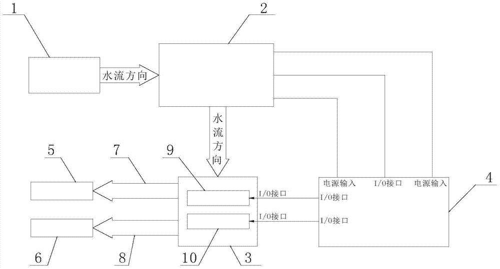
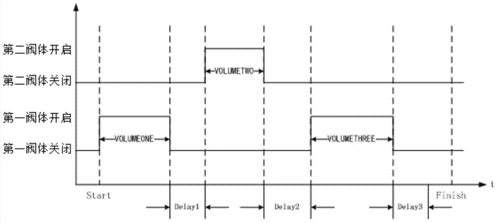
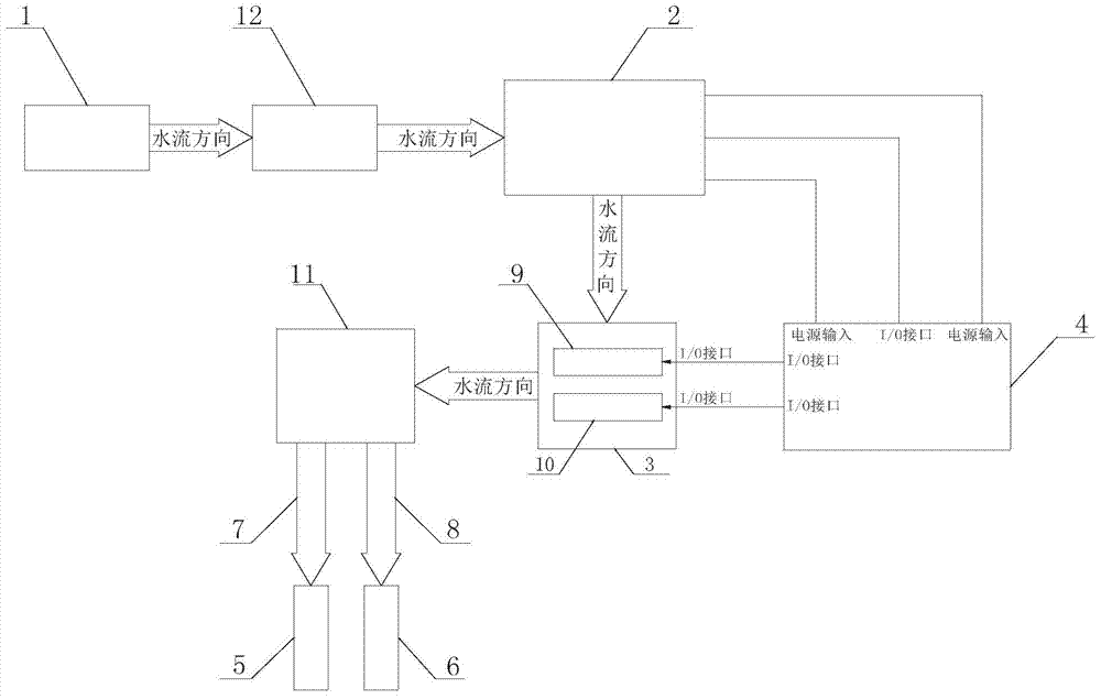
[0039] The first embodiment of the present invention relates to a water volume control system for a toilet, such as figure 1 As shown, it includes a sensor 2 arranged at the water inlet end 1 of the toilet, and a control valve 3 arranged at the water outlet end of the toilet. Wherein, the toilet water inlet 1 is connected w...


PUM


Abstract

The invention relates to a system and method for controlling the water quantity of a closestool. The system comprises a sensor arranged at the water inlet end of the closestool and a control valve arranged at the water outlet end of the closestool, and the water inlet end of the closestool is communicated with the water outlet end of the closestool through the sensor and the control valve in sequence. The system for controlling the water quantity of the closestool further comprises a control circuit board connected with the sensor and the control valve. Compared with the prior art, the sensor can regularly detect water flow parameters of the water inlet end of the closestool, the control circuit board is responsible for collecting the water flow parameter values detected by the sensor and sending corresponding control signals to the control valve after analyzing relevant parameter values, and then the control valve is opened or closed according to the obtained control signals. When the quantity of water flowing out of the control valve reaches the preset water quality after the control valve is opened, the control valve is closed through the control circuit board, and therefore the rated water quantity of the closestool is achieved accurately, and the best flushing effect is achieved.

Description

technical field [0001] The invention relates to a toilet, in particular to a water volume control system and a control method of the toilet. Background technique [0002] The flush toilet, as a kind of sewage device, its basic principle is to use the gravity of water to convert the potential energy of water into the kinetic energy of water, so as to carry the excreted dirt into the sewer pipe to complete the whole process of sewage discharge. Moreover, with the advancement of technology, the flush toilet has also developed from the most primitive manual type to today's electric type. [0003] Since the electric toilet is currently a relatively high-end product, its convenience and comfort are self-evident. At present, most electric toilets that use direct water supply generally realize the flushing function of the toilet by adjusting the opening time of the solenoid valve. However, due to the uncertainty of the water pressure in the tap water pipe, it will be found in use ...

Claims


Application Information

Patent Timeline
IPC IPC(8): E03D5/10
Inventor 胡小兰
Owner KOHLER CHINA INVESTMENT
Learn More