
Novel adjustable sealing ball valve with high pressure releasing function

A technology of relief and function, applied in the direction of valve devices, cocks including cut-off devices, engine components, etc., can solve the problems of limited adjustment ability, limited adjustment amount, and difficulty in consistency, etc., to achieve extended service life and high pressure bearing capacity , the effect of a large amount of adjustment

Active Publication Date: 2015-01-07
BEIJING INST OF AEROSPACE TESTING TECH
View PDF7 Cites 1 Cited by
  • Summary
  • Abstract
  • Description
  • Claims
  • Application Information

AI Technical Summary

Problems solved by technology

This method has the following disadvantages: First, it is difficult to adjust evenly, because multiple adjustment points are arranged on the circumference, each adjustment point is adjusted separately, it is difficult to adjust them all in a consistent manner, and if there is any inconsistency, it will cause Uneven force distribution on the valve seat causes partial leakage
Secondly, the adjustment ability is limited, limited to the size of the valve body and the cone surface, the adjustment amount in the axial direction of the valve is very limited, and it cannot be continuously adjusted
Again, opening multiple holes will reduce the strength of the valve body

Method used


Image

  • Novel adjustable sealing ball valve with high pressure releasing function
  • Novel adjustable sealing ball valve with high pressure releasing function
  • Novel adjustable sealing ball valve with high pressure releasing function

Examples


Embodiment 1

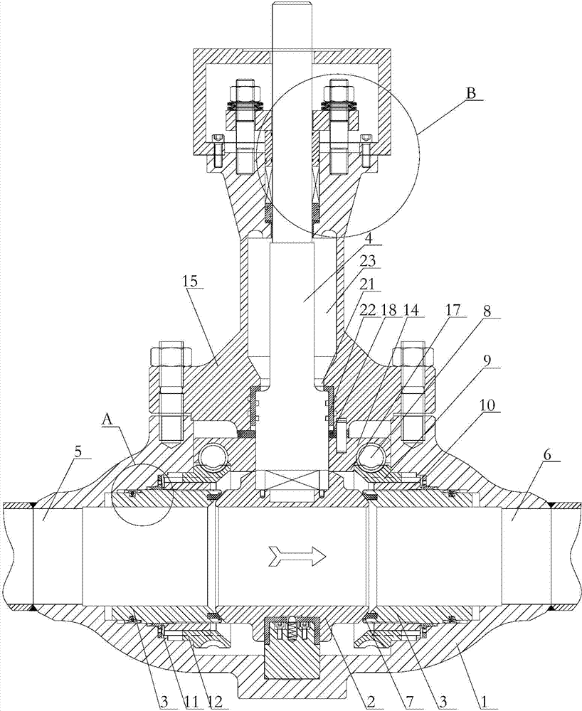
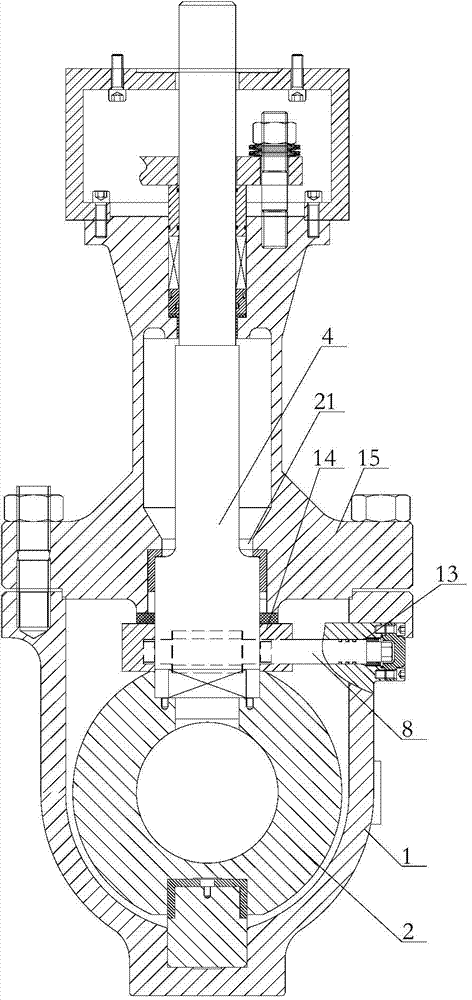
[0041] Embodiment 1 of the present invention: a new type of sealed adjustable ball valve with high pressure relief function, such as figure 1 and figure 2 As shown, it includes a valve body 1, a ball 2, a valve seat 3 and a valve stem 4 that drives the ball 2 to rotate;

[0042] The valve body 1 is a cavity structure, and the valve body 1 is provided with an inlet fluid channel 5 and an outlet fluid channel 6 communicating with the cavity, and the ball 2 is arranged on the inlet fluid channel 5 and the outlet between fluid passages 6;

[0043] The ball 2 is rotatably arranged in the cavity of the valve body 1; one end of the valve rod 4 penetrates into the valve body 1 and is fixedly connected with the ball 2;

[0044] The valve seat 3 is rotatably arranged in the cavity of the valve body 1 where the inlet fluid passage 5 and the outlet fluid passage 6 are connected;

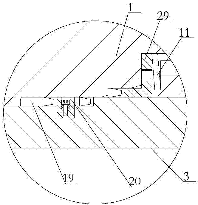
[0045] The upper ring of the valve seat 3 is provided with a sealing ring 7 that can block the connection...

Embodiment 2

[0062] Embodiment 2 of the present invention: a novel sealed adjustable ball valve with high pressure relief function, including a valve body 1, a ball 2, a valve seat 3 and a valve stem 4 that drives the ball 2 to rotate;

[0063] The valve body 1 is a cavity structure, and the valve body 1 is provided with an inlet fluid channel 5 and an outlet fluid channel 6 communicating with the cavity, and the ball 2 is arranged on the inlet fluid channel 5 and the outlet between fluid passages 6;

[0064] The ball 2 is rotatably arranged in the cavity of the valve body 1; one end of the valve rod 4 penetrates into the valve body 1 and is fixedly connected with the ball 2;

[0065] The valve seat 3 is rotatably arranged in the cavity of the valve body 1 where the inlet fluid passage 5 and the outlet fluid passage 6 are connected;

[0066] The upper ring of the valve seat 3 is provided with a sealing ring 7 that can block the connection between the internal flow channel of the ball 2 an...

Embodiment 3

[0077] Embodiment 3 of the present invention: a novel sealing and adjustable ball valve with high-pressure relief function, including a valve body 1, a ball 2, a valve seat 3 and a valve stem 4 that drives the ball 2 to rotate;

[0078] The valve body 1 is a cavity structure, and the valve body 1 is provided with an inlet fluid channel 5 and an outlet fluid channel 6 communicating with the cavity, and the ball 2 is arranged on the inlet fluid channel 5 and the outlet between fluid passages 6;

[0079] The ball 2 is rotatably arranged in the cavity of the valve body 1; one end of the valve rod 4 penetrates into the valve body 1 and is fixedly connected with the ball 2;

[0080] The valve seat 3 is rotatably arranged in the cavity of the valve body 1 where the inlet fluid passage 5 and the outlet fluid passage 6 are connected;

[0081] The upper ring of the valve seat 3 is provided with a sealing ring 7 that can block the connection between the internal flow channel of the ball...


PUM


Abstract

The invention relates to a novel adjustable sealing ball valve with a high pressure releasing function. The novel adjustable sealing ball valve with the high pressure releasing function comprises a valve body, a ball body, a valve seat and a valve rod driving the ball body to rotate. The valve seat can slide relative to the valve seat and is arranged inside the cavity of the valve body which is communicated with an inlet flow channel and an outlet flow channel; the upper ring of the valve body is provided with a sealing ring capable of plugging the communicating portion of the internal flow channel of the ball body and the cavity of the valve body, the ring-shaped outer walls of the valve seat portions of the inlet flow channel and the outlet flow channel are rotatably connected with the valve body in a matched mode, and parts of the outer walls are connected in a sealed mode with the valve body through ring-shaped sealing modules; each ring-shaped sealing module is composed of at least one one-way sealing ring, and the slots of at least one one-way sealing ring on the valve seat are in the same direction and back to the ball body. By means of the one-way sealing rings arranged between the valve seat and the valve body, the novel adjustable sealing ball valve achieves the pressure releasing function, thereby solving the problem of damage due to high pressure inside the valve body and prolonging the service life, and meanwhile, by means of a worm and gear driving mechanism, achieves an sealing adjustable function.

Description

technical field [0001] The invention relates to a ball valve, in particular to a novel sealing adjustable ball valve with a high-pressure release function. Background technique [0002] As a globe valve to control the pipeline, the ball valve has a wide range of applications, and there are different requirements for the function of the ball valve in different technical fields. In the transmission process of liquefied petroleum gas or gas, the liquefied gas is very easy to vaporize. For example, when the ball valve blocks the flow channel of the medium, some medium will remain in the channel inside the ball valve and enter the valve body. In the cavity, if the residual medium vaporizes, a high internal pressure will be generated in the valve body. If the pressure is not released in time, it may cause damage to the valve body of the ball valve, and may even cause a safety accident, such as , The volume of liquefied natural gas (LNG) expands to 600 times after gasification. If...

Claims


Application Information

Patent Timeline
Patent Type & Authority Applications(China)
IPC IPC(8): F16K5/06F16K5/20F16K5/08
CPCF16K5/0673F16K5/0689F16K5/08F16K5/20
Inventor 滕磊军任宏杰孙拥军施晓丽于兰李亚鹏申靖
Owner BEIJING INST OF AEROSPACE TESTING TECH
Learn More