Multifunctional power panel testing production line

A power board and production line technology, applied in the direction of electronic circuit testing, measuring device casing, sorting, etc., can solve PCBA unqualified problems, achieve stable quality, solve PCBA unqualified, improve work efficiency and automate the effect

Active Publication Date: 2015-01-07
DONGGUAN GUANJIA ELECTRONICS EQUIP
View PDF5 Cites 21 Cited by
  • Summary
  • Abstract
  • Description
  • Claims
  • Application Information

AI Technical Summary

Problems solved by technology

[0003] The purpose of the present invention is to: aim at the deficiencies in the prior art, and provide a kind of multifunctional power supply board test production line, this test line has solved the PCBA unqualified problem that some artificial or uncertain factors cause, and has improved PCBA test High work efficiency makes the quality of PCBA testing more stable

Method used


Image

  • Multifunctional power panel testing production line
  • Multifunctional power panel testing production line
  • Multifunctional power panel testing production line

Examples


Embodiment 1

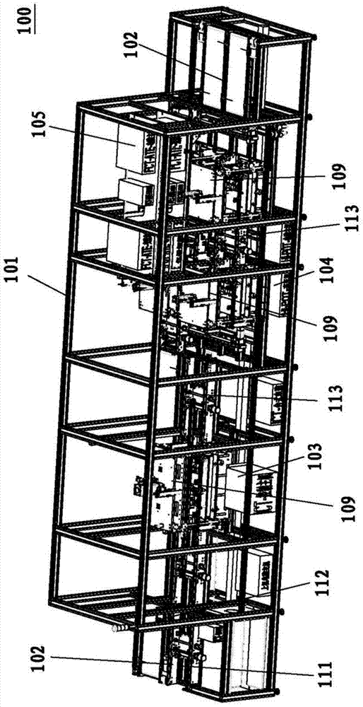
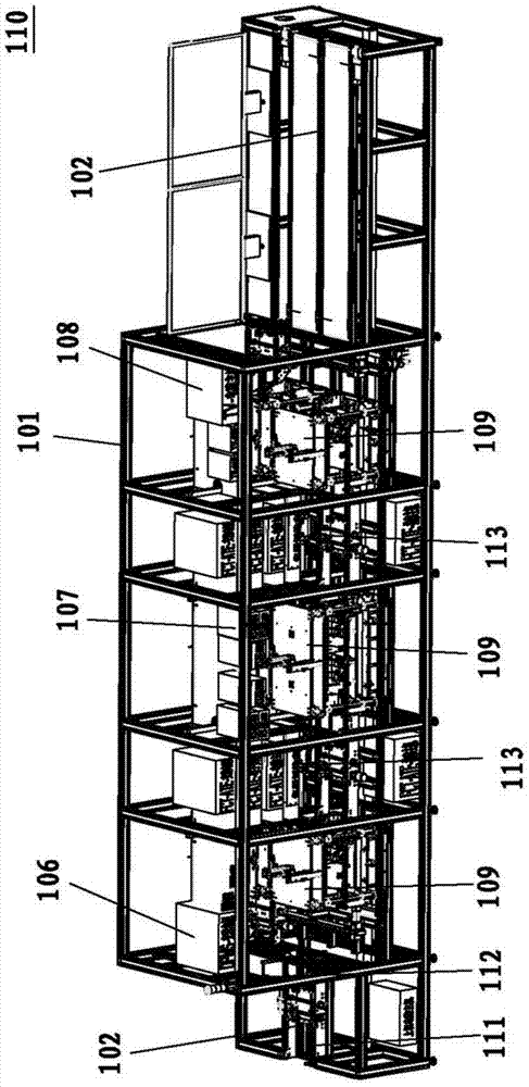
[0025] Embodiment 1, reference figure 1 and figure 2 , a multifunctional power board testing production line, comprising a first testing device 100 and a second testing device 110, the power board flows through the first testing device 100 and then enters the second testing device 110, the first testing device 100 and the second testing device 110 The devices 110 all include a frame 101, a conveyor belt 102 across the frame 101, and a test fixture 109 arranged on the frame 101; the first test device 100 also includes an ICT test mechanism 103, a Hi-pot test mechanism 104 and an FCT The testing mechanism 105, the ICT testing mechanism 103, the Hi-pot testing mechanism 104 and the FCT testing mechanism 105 are successively arranged on the frame 101 of the first testing device 100; the second testing device 110 also includes a DPMS testing mechanism 106, an ATE testing mechanism 107 and The TV test mechanism 108 , the DPMS test mechanism 106 , the ATE test mechanism 107 and the...

Embodiment 2

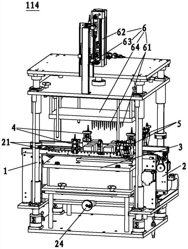
[0030] Embodiment 2, refer to Figure 4 and Figure 8 , the difference from Embodiment 1 is that the test fixture 109 of this embodiment is set as a double power supply board test fixture 115, and the double power supply board test fixture 115 is provided with a synchronous scraper mechanism 7, and a synchronous scraper mechanism 7 Including a synchronous frame 71, a synchronous cylinder 72, a synchronous motor 73, a synchronous belt 74, a synchronous wheel 75 and an origin sensor 76, the synchronous frame 71 includes a synchronous track 77, a support portion 78 arranged on the top of the synchronous track 77 and a support portion 78 fixed The top plate 79, the synchronous cylinder 72 is arranged on the top plate 79, the synchronous motor 73 is arranged on the support portion 78, the synchronous belt 74, the synchronous wheel 75 and the origin sensor 76 are all arranged on the synchronous track 77. The synchronous track 77 is provided with a first locking position 771 and a s...


PUM


Abstract

The invention discloses a multifunctional power panel testing production line. The multifunctional power panel testing production line comprises a first testing device and a second testing device. A power panel enters the second testing device after passing through the first testing device. The first testing device and the second testing device each comprise a rack, a conveyer belt stretching across the rack and a testing fixture arranged on the rack. The first testing device further comprises an ICT testing mechanism, a Hi-pot testing mechanism and an FCT testing mechanism, and the ICT testing mechanism, the Hi-pot testing mechanism and the FCT testing mechanism are sequentially arranged on the rack of the first testing device. The second testing device further comprises a DPMS testing mechanism, an ATE testing mechanism and a TV testing mechanism, and the DPMS testing mechanism, the ATE testing mechanism and the TV testing mechanism are sequentially arranged on the rack of the second testing device. The multifunctional power panel testing production line improves the working efficiency and automation of PCBA tests and makes the quality of the PCBA tests more stable.

Description

technical field [0001] The invention belongs to the technical field of testing equipment, and in particular relates to a multifunctional power board testing production line. Background technique [0002] PCBA is the abbreviation of Printed Circuit Board+Assembly in English, that is, on the empty PCB board, first go through the SMT (surface mount technology) upper part, and then go through the production process of the DIP (dual in-line packaging technology) plug-in. PCBA boards have been widely used before the industrial age, and it is the core of computers and embedded systems. Since the production of PCBA is in the second half of electronic equipment manufacturing, it is regarded as the downstream industry of the electronics industry. Almost all electronic devices require the support of printed circuit boards, so printed circuit boards have the highest market share among electronic components in the world. At present, Japan, China, Taiwan, Western Europe and the United S...

Claims


Application Information

Patent Timeline
Patent Type & Authority Applications(China)
IPC IPC(8): G01R31/28G01R1/04B07C5/344
Inventor 李垂猛翟保利
Owner DONGGUAN GUANJIA ELECTRONICS EQUIP
Why Eureka
Try Eureka