Linear frequency-modulated signal generator with predistortion function

A technology of linear frequency modulation signal and frequency modulation signal, which is applied in the direction of instruments, oscillation conversion angle demodulation, radio wave measurement system, etc. It can solve the problems of large area and power consumption, large number of DRAMs, and many connections, etc., to achieve area and power Low power consumption, reduced design difficulty, and improved integration

Active Publication Date: 2015-01-07
INST OF ELECTRONICS CHINESE ACAD OF SCI
View PDF6 Cites 17 Cited by
  • Summary
  • Abstract
  • Description
  • Claims
  • Application Information

AI Technical Summary

Problems solved by technology

The problems caused by the expansion of large-capacity and high-speed DRAMs are: (1) poor signal quality; (2) in order to meet the conversion speed requirements of high-speed DACs, a large number of DRAMs is required; (3) there are many connections with the FPGA, which takes up a lot of IO resources; (4) The control of DRAM is complex, especially the need to implement dual ports; (5) The structure is complex, the area and power consumption are relatively large, and the resulting cost is also high

Method used


Image

  • Linear frequency-modulated signal generator with predistortion function
  • Linear frequency-modulated signal generator with predistortion function
  • Linear frequency-modulated signal generator with predistortion function

Examples


Embodiment Construction

[0025] In order to make the object, technical solution and advantages of the present invention clearer, the present invention will be described in further detail below in conjunction with specific embodiments and with reference to the accompanying drawings. It should be noted that, in the drawings or descriptions of the specification, similar or identical parts all use the same figure numbers. Implementations not shown or described in the accompanying drawings are forms known to those of ordinary skill in the art. Additionally, while illustrations of parameters including particular values ​​may be provided herein, it should be understood that the parameters need not be exactly equal to the corresponding values, but rather may approximate the corresponding values ​​within acceptable error margins or design constraints.

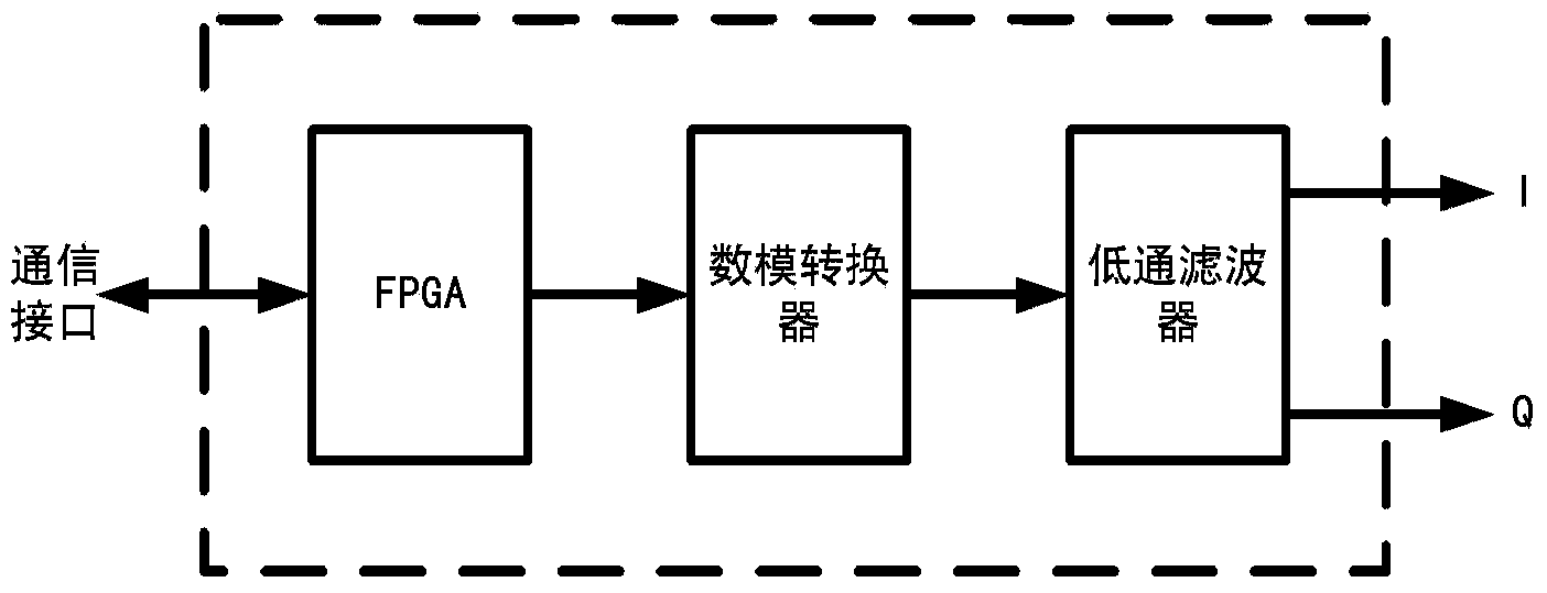
[0026] In an exemplary embodiment of the present invention, a chirp signal generator with predistortion function is provided. figure 1 It is a block diagram o...


PUM


Abstract

The invention provides a linear frequency-modulated signal generator with a predistortion function. The linear frequency-modulated signal generator comprises an FPGA unit, a digital-analog conversion unit and a filtering unit, wherein the FPGA unit is used for generating a phase position predistortion digital linear frequency-modulated signal and conducting amplitude predistortion processing on the phase position predistortion digital linear frequency-modulated signal to generate two orthogonal amplitude-phase predistortion digital linear frequency-modulated signals; the digital-analog conversion unit is connected with the output end of the FPGA unit and used for converting the two orthogonal digital linear frequency-modulated signals subjected to amplitude-phase predistortion into two orthogonal discrete analog linear frequency-modulated signals; the filtering unit is connected with the digital-analog conversion unit and used for filtering out frequency components beyond a preset frequency range of the two orthogonal discrete analog linear frequency-modulated signals to obtain two continuous orthogonal analog linear frequency-modulated signals. The linear frequency-modulated signal generator can compensate for non-linear influences of an analog circuit on the linear frequency-modulated signals by means of amplitude-phase predistortion processing, and guarantee that the high-quality linear frequency-modulated signals can be obtained finally.

Description

technical field [0001] The invention relates to the technical field of electronic components in the electronics industry, in particular to a chirp signal generator with a pre-distortion function. Background technique [0002] The linear frequency modulation signal refers to the linear relationship between the frequency and time of the signal. It uses phase modulation and pulse compression technology to reduce the peak power of the transmitter and increase the radar range. This advantage makes it widely used in the field of synthetic aperture radar, and how to generate chirp signals has become a hot spot in theoretical and engineering research. [0003] There are two traditional methods for generating chirp signals: digital waveform direct synthesizer and digital waveform storage direct reading method. Their advantages and disadvantages are as follows: [0004] 1) Digital Waveform Direct Synthesizer (Direct Digital Synthesis-DDS) can generate high-quality single-pulse chirp ...

Claims


Application Information

Patent Timeline
Patent Type & Authority Applications(China)
IPC IPC(8): G01S7/40
CPCG01S7/35H03D3/007
Inventor 李和平朱建光张弛高维波张建龙
Owner INST OF ELECTRONICS CHINESE ACAD OF SCI
Why Eureka
Try Eureka