
A Construction Method and Application of Inverter Dead Zone Voltage Compensation Model

A technology of dead zone voltage and compensation method, which is applied in the direction of converting irreversible DC power input into AC power output, electrical components, control generators, etc. Repeated calibration work, self-adaptive accurate compensation, and the effect of avoiding compensation errors

Active Publication Date: 2022-06-21
HUAZHONG UNIV OF SCI & TECH
View PDF0 Cites 0 Cited by
  • Summary
  • Abstract
  • Description
  • Claims
  • Application Information

AI Technical Summary

Problems solved by technology

[0004] Aiming at the above defects or improvement needs of the prior art, the present invention provides a method for constructing an inverter dead-zone voltage compensation model and its application to solve the non-linear effect on the inverter that cannot be adaptive in the prior art Technical Issues for Accurate Compensation

Method used


Image

  • A Construction Method and Application of Inverter Dead Zone Voltage Compensation Model
  • A Construction Method and Application of Inverter Dead Zone Voltage Compensation Model
  • A Construction Method and Application of Inverter Dead Zone Voltage Compensation Model

Examples


Embodiment 1

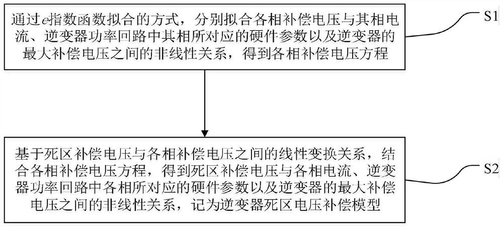
[0051] A construction method of inverter dead zone voltage compensation model, such as figure 1 shown, including the following steps:

[0052] S1. Fit the nonlinear relationship between the compensation voltage of each phase and its phase current, the hardware parameters corresponding to its phase in the inverter power loop, and the maximum compensation voltage of the inverter by means of e-exponential function fitting. Obtain the compensation voltage equation of each phase;

[0053] Specifically, considering that the corresponding hardware parameters in the inverter power loop are different, the present invention obtains the compensation voltage equations of each phase by fitting by means of the e-exponential function respectively;

[0054] Among them, the m-th phase compensation voltage equation is:

[0055]

[0056] where m is a or b or c; ΔV m is the compensation voltage of the mth phase; V d is the maximum compensation voltage of the inverter; w m is the hardware ...

Embodiment 2

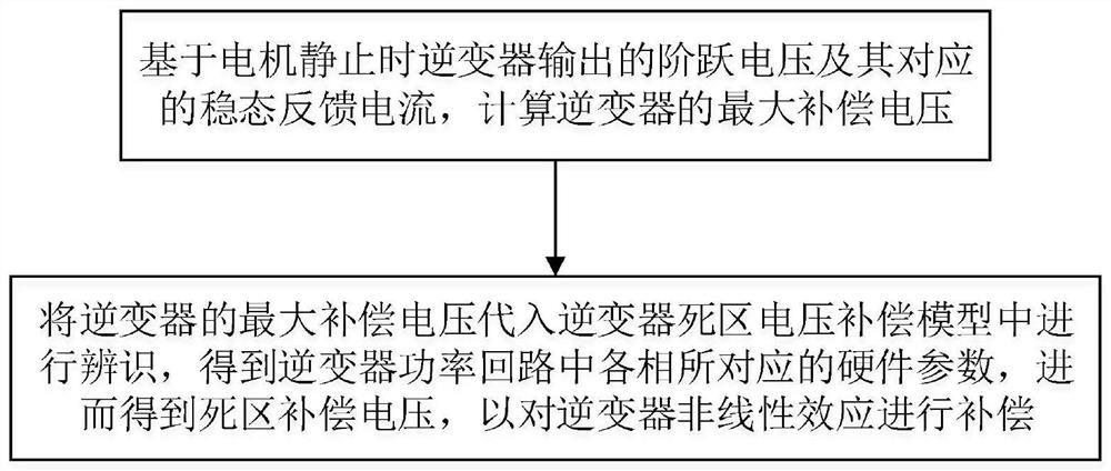
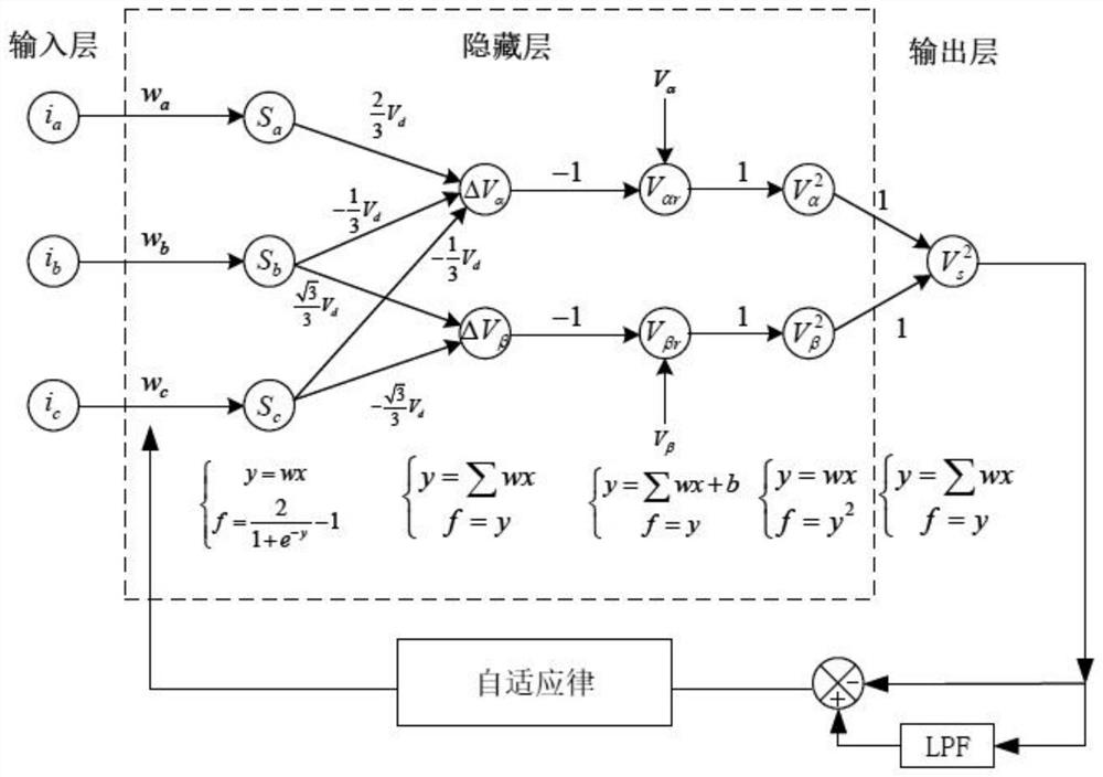
[0074] A non-linear effect compensation method of an inverter includes a maximum compensation voltage identification unit and an identification unit. The maximum compensation voltage identification unit is used to identify the maximum compensation voltage according to the output of two different step voltages when the motor is stationary. The identification unit is used to identify the dead zone voltage compensation model of the inverter obtained in Embodiment 1 when the motor is running, so as to realize adaptive compensation for the nonlinear effect of the inverter. Specifically, when the motor is running, the identification unit uses the equivalent dead zone compensation voltage to describe the voltage distortion caused by the nonlinear effect of the inverter, performs online identification of the inverter dead zone voltage compensation model, and then performs an online identification of the inverter dead zone voltage compensation model according to the identified model. c...


PUM


Abstract

The invention discloses a method for constructing an inverter dead-zone voltage compensation model and its application, including: S1, fitting the compensation voltage of each phase and its phase current, and the power circuit of the inverter respectively by means of e-exponential function fitting Among them, the nonlinear relationship between the hardware parameters corresponding to the phases and the maximum compensation voltage of the inverter is obtained, and the compensation voltage equation of each phase is obtained; S2, based on the linear transformation relationship between the dead zone compensation voltage and the compensation voltage of each phase, combined with Compensation voltage equation of each phase, get the nonlinear relationship between the compensation voltage in the dead zone and the current of each phase, the hardware parameters corresponding to each phase in the power loop of the inverter, and the maximum compensation voltage of the inverter, which is recorded as the dead zone of the inverter Area voltage compensation model. The present invention does not need to use the electrical parameters of the inverter, and also avoids the compensation error of the traditional compensation algorithm and the cumbersome theoretical model calculation, can obtain better compensation effect, and can real-time and self-adaptive to the inverter Linear effects are precisely compensated.

Description

technical field [0001] The invention belongs to the field of motor control, and more particularly, relates to a construction method of an inverter dead zone voltage compensation model and its application. Background technique [0002] With the development of science and technology, more and more power electronic products have been applied to people's daily production and life. The inverter is an important application in the power electronics industry. Its main function is to convert direct current into alternating current. As a common inverter, three-phase inverters are widely used in various motor drive control systems. However, in order to avoid the direct connection of the upper and lower tubes of the same bridge arm of the three-phase inverter, dead time is inserted, and the power devices have on-off switches. Non-linear effects such as turn-off delay and tube voltage drop can easily lead to distortion of the actual output voltage and reference voltage, resulting in the ...

Claims


Application Information

Patent Timeline
Patent Type & Authority Patents(China)
IPC IPC(8): H02P21/14H02M7/48H02M1/38
CPCH02P21/14H02M7/48H02M1/38
Inventor 童乔凌刘涛闵闰
Owner HUAZHONG UNIV OF SCI & TECH
Learn More