
Lag angle compensation device and lag angle compensation precision correction method of satellite-borne wind-detecting laser radar system

A technology of wind measurement laser radar and compensation device, which is applied in the field of measurement, and can solve the problems of lag angle failure and compensation

Inactive Publication Date: 2015-01-07
BEIJING INSTITUTE OF TECHNOLOGYGY
View PDF5 Cites 15 Cited by
  • Summary
  • Abstract
  • Description
  • Claims
  • Application Information

AI Technical Summary

Problems solved by technology

The scanning method of the double telescope will cause two kinds of deviations in the optical axis of the echo beam, that is, the optical axis of the echo beam is located above or below the theoretical optical axis of the receiving system, so that the lag angle cannot be compensated by a fixed device

Method used


Image

  • Lag angle compensation device and lag angle compensation precision correction method of satellite-borne wind-detecting laser radar system
  • Lag angle compensation device and lag angle compensation precision correction method of satellite-borne wind-detecting laser radar system
  • Lag angle compensation device and lag angle compensation precision correction method of satellite-borne wind-detecting laser radar system

Examples


Embodiment Construction

[0042] In order to better illustrate the technical solution of the present invention, the present invention will be further described below through examples and accompanying drawings.

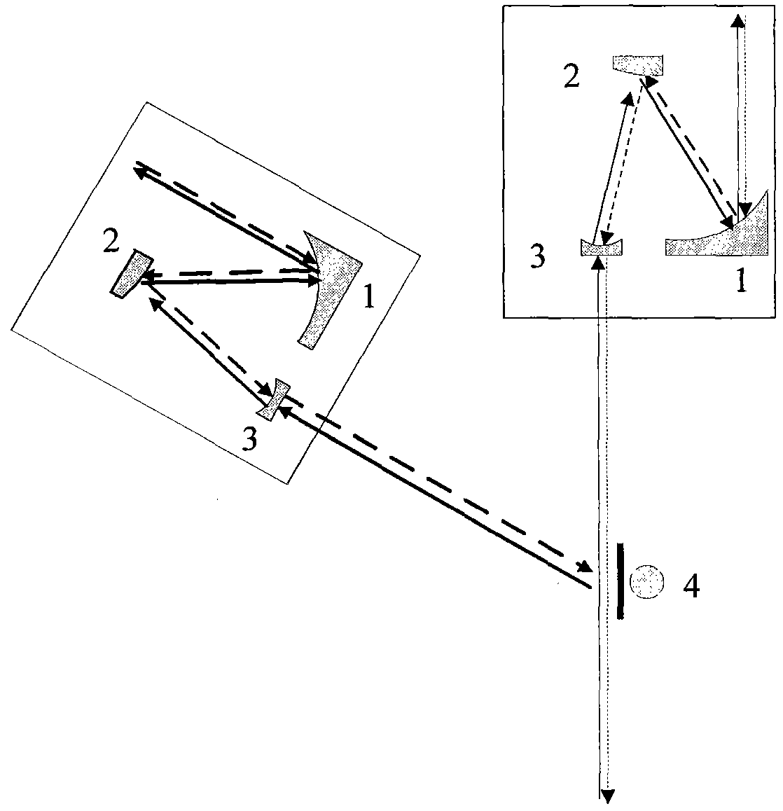
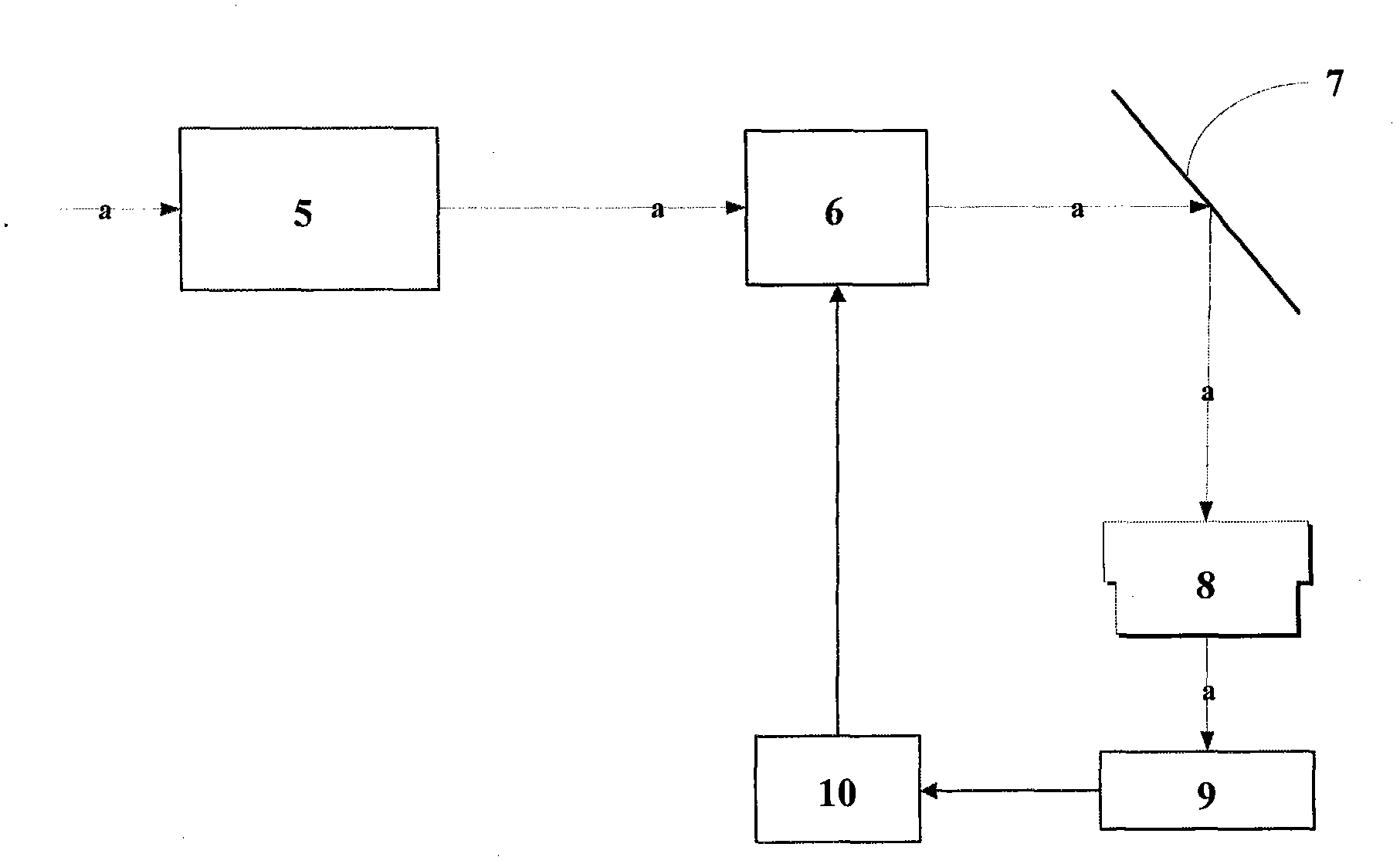
[0043] The lag angle compensation device of the spaceborne wind-measuring lidar system in this embodiment has a structure such as figure 1 As shown, it includes: a telescope scanning optical system 5 , a lag angle compensation module 6 , a movable insert mirror 7 , a beam expander 8 , an area array photodetector 9 and a control signal processing module 10 . figure 1 Among them, a represents the system optical axis of the lag angle compensation device of the spaceborne lidar wind measurement system.

[0044] The telescope scanning optical system 5 includes: a scanning controller 4 and two identical off-axis reflecting telescopes W 1 and W 2 ; off-axis reflecting telescope W 1 The optical axis of the system is parallel to the system optical axis a of the lagging angle compensation device of th...


PUM


Abstract

The invention relates to a lag angle compensation device and a lag angle compensation precision correction method of a satellite-borne wind-detecting laser radar system and belongs to the field of measuring technologies. A lag angle compensation module inside the device is located behind a double-telescope optical scanning system; when a system normally works, echo lasers are transmitted to the lag angle compensation module through the double-telescope optical scanning system and then transmitted to peripheral equipment after compensation of the lag angle compensation module; in the process of lag angle compensation precision correction, a movable insertion type reflection mirror is located on the optical path behind the lag angle compensation module, and a beam expander is placed on one side of the movable insertion type reflection mirror and located at the front end of an area array photoelectric detector; the output end of the area array photoelectric detector is connected with the input end of a control signal processing module; the output end of the control signal processing module is connected with the input end of the lag angle compensation module. The lag angle compensation device and the lag angle compensation precision correction method of the satellite-borne wind-detecting laser radar system have the advantages of being dynamically adjustable in compensation angle and capable of using closed loop detection for precise correction.

Description

technical field [0001] The invention relates to a lag angle compensation device and an accuracy correction method, in particular to a lag angle compensation device and an accuracy correction method for a spaceborne laser radar wind measurement system, and belongs to the field of measurement technology. Background technique [0002] Laser Doppler wind radar is a technology that uses the Doppler effect of light to measure the velocity of atmospheric wind field. It performs heterodyne beat frequency between the echo containing wind speed information and local oscillator light to calculate the wind speed at different distances. It has the characteristics of high sensitivity and high speed accuracy. It can measure clear air turbulence, wind shear, aircraft trajectory vortex, etc., in It has broad application prospects in fields such as weather forecasting, environmental monitoring, aerospace, remote sensing and telemetry, and meteorological observation. The orbital altitude of t...

Claims


Application Information

Patent Timeline
IPC IPC(8): G01S7/48G01S7/481
CPCG01S7/48G01S7/4817
Inventor 郭磐张寅超杨志浩陈思颖陈和
Owner BEIJING INSTITUTE OF TECHNOLOGYGY
Learn More