
Cylindrical battery cap

A cylindrical, battery technology, applied in the field of battery caps, can solve problems such as changing the working state, leakage, rupture of the aluminum film of the opening layer, etc., to achieve the effect of improving safety performance

Inactive Publication Date: 2015-01-07
SUZHOU ANKAO ENERGY
View PDF6 Cites 3 Cited by
  • Summary
  • Abstract
  • Description
  • Claims
  • Application Information

AI Technical Summary

Problems solved by technology

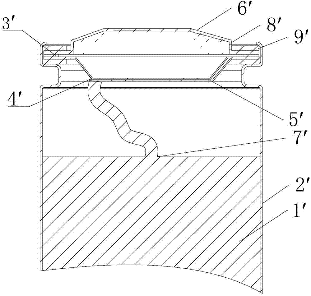
For example, 1. The rigidity of the cap is very good. When the batteries are connected in series and parallel to each other, it is possible that multiple batteries are pressed on the cap. It is fully transmitted to the sealing ring 9', and the sealing ring 9' is subjected to a large external force, which will change its working state, cause the sealing quality to decline, and there will be a danger of leakage after a long time
2. If the pressure is too high and the top of the cap sinks, it may be pressed to the opening layer below, causing the aluminum film of the opening layer to rupture and the seal to fail
4. If the welding energy is too large during laser welding on the top of the cover, there is a danger of burning through the top layer of the cover, and the penetrating laser beam will burn further down to open the aluminum film
Since aluminum has a much lower melting point than steel, the laser beam can easily burn through it, rendering the battery seal completely useless
What's more dangerous is that this kind of damage can't be seen on the outside at all. If the battery is put into the battery pack, the electrolyte will dry up due to air leakage and liquid leakage, and the battery will fail, which will inevitably cause early damage to the entire battery pack.

Method used


Image

  • Cylindrical battery cap
  • Cylindrical battery cap
  • Cylindrical battery cap

Examples


Embodiment Construction

[0025] The present invention will be further described below in conjunction with specific examples, but the present invention is not limited to these specific embodiments. Those skilled in the art should realize that the present invention covers all alternatives, improvements and equivalents that may be included within the scope of the claims.

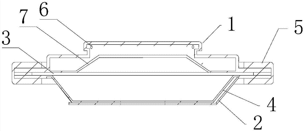
[0026] Reference figure 2 , image 3 , A cylindrical battery cap, which is installed at the sealing of the battery steel shell, and includes a cap head 1 and a base 2. A gasket 3 is arranged between the cap head 1 and the base 2, and the base 2 is covered with explosion-proof Open the aluminum film 4, the joint between the cap head 1 and the base 2 is covered with a sealing ring 5, the side of the cap head 1 is provided with a plurality of exhaust holes 6, and the side of the cap head 1 is provided with Anti-vibration structure with axial stretchability. The present invention is provided with an anti-vibration structure on the side of t...


PUM


Abstract

The invention provides a cylindrical battery cap which is mounted at a seal of a steel battery shell. The cylindrical battery cap comprises a cap head and a base, wherein a gasket is arranged between the cap head and the base; an anti-explosion opening aluminum film covers the base; a joint of the cap head and the base is coated with a sealing ring; a plurality of exhaust holes are formed in the side surface of the cap head; an anti-vibration structure capable of endowing axial elasticity on the cap head is arranged on the side surface of the cap head. The anti-vibration structure is arranged on the side surface of the cap head, so that the cap head has certain axial elasticity; under the action of an external force, a part of mechanical vibration impact force can be well released, pressure on the sealing ring is alleviated, the sealing ring is prevented from being damaged, and the safety is improved.

Description

Technical field [0001] The invention relates to a cylindrical battery cap. Background technique [0002] Lithium-ion batteries are widely used because of their high specific energy, high specific power, long cycle life, and no toxic substances. Especially cylindrical lithium-ion batteries, which are durable, well-sealed, and easy to combine in series and parallel. Many of its models have the same dimensions as dry batteries, nickel-cadmium batteries, and nickel-metal hydride batteries. They are extremely easy to replace and use, and they are more widely used. Therefore, it is very meaningful to improve it to make it safer and more reliable. [0003] Existing cylindrical lithium-ion batteries generally use caps as the positive terminal, and the positive terminal has a structure like figure 1 As shown, the electrode assembly 1'is installed in the steel shell 2', and the positive lug 7'is drawn from the electrode assembly and welded to the cap base 5'. The explosion-proof opening alu...

Claims


Application Information

Patent Timeline
Patent Type & Authority Applications(China)
IPC IPC(8): H01M2/04H01M2/10H01M2/30
CPCH01M10/0525H01M50/147H01M50/543Y02E60/10
Inventor 许玉林王爱淑
Owner SUZHOU ANKAO ENERGY
Learn More