Satellite data transmission antenna with wide beam and even gain advantages

A technology of satellite data transmission and wide beam, applied in the field of aerospace engineering, can solve the problem that the data transmission antenna cannot achieve uniform gain of wide beam

Active Publication Date: 2015-01-07
NAT SPACE SCI CENT CAS
View PDF4 Cites 8 Cited by
  • Summary
  • Abstract
  • Description
  • Claims
  • Application Information

AI Technical Summary

Problems solved by technology

[0003] The object of the present invention is, in order to solve the beam requirement that the existing digital transmission antenna cannot realize the uniform gain of the wide beam, the present invention provides a satellite data transmission antenna with uniform gain of the wide beam

Method used


Image

  • Satellite data transmission antenna with wide beam and even gain advantages
  • Satellite data transmission antenna with wide beam and even gain advantages
  • Satellite data transmission antenna with wide beam and even gain advantages

Examples


Embodiment Construction

[0017] A satellite data transmission antenna with wide beam uniform gain according to the present invention will be described in detail below in conjunction with the accompanying drawings and embodiments.

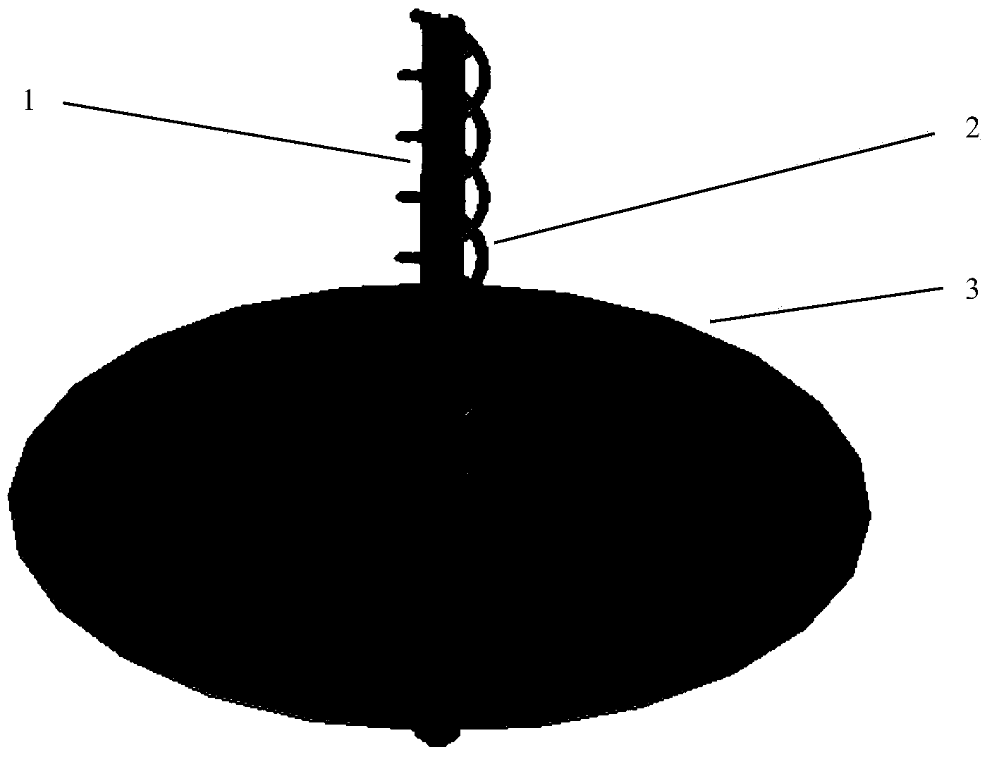
[0018] In the present invention, the satellite data transmission antenna body structure with wide beam uniform gain is as follows: figure 1 As shown, the satellite data transmission antenna adopts a double helix antenna structure, and is fed through the provided coaxial line 1, and the feed is at the top of the antenna.

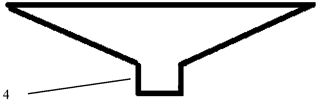
[0019] In this embodiment, the top of the inner conductor of the coaxial line is welded on the inner wall of the outer conductor, and the top of the outer conductor may be provided with two symmetrical grooves as a balun structure of the satellite data transmission antenna. The two helical wires provided in the satellite data transmission antenna are symmetrically welded to the top of the outer conductor to form equal-amplitude and opposite-phase feeds to ...


PUM


Abstract

The invention provides a satellite data transmission antenna with the wide beam and even gain advantages. The satellite data transmission antenna is of a double-helical-antenna structure and carries out feed through a coaxial line (1). The satellite data transmission antenna is characterized in that a conical reflector cup (3) is arranged at the bottom end of the coaxial line (1) in a penetrating mode, and a concave hole (4) is formed in the bottom of the conical reflector cup (3). The satellite data transmission antenna is provided with the conical reflector cup, so that influence on the antenna from reflection of a satellite deck is reduced; for a small ground proximity detector, the antenna has the even gain distribution within the required beam range by designing parameters of helical antennas, and meanwhile gains not within the beam range can be rapidly decreased; the small antenna has the wide beam and even gain advantages.

Description

technical field [0001] The invention relates to the technical field of aerospace engineering, in particular to a satellite data transmission antenna with wide beam uniform gain. Background technique [0002] Usually, in order to achieve data transmission and communication with the ground station, the antenna of the near-Earth detector is installed on the directional surface of the ground. The satellite needs to consume energy to keep the antenna always facing the earth, and the antenna beam is a saddle-shaped shaped beam, and the beam gain is in the center. is sunken. Especially for small satellites, due to their limited energy, and while transmitting data to the ground, it is required to keep their attitude unchanged for detection activities (such as observing stars, measuring magnetic fields, etc.), at this time, the attitude of some satellites is generally The inertial orientation is maintained, and the antenna pointing remains unchanged in space. Therefore, the previous...

Claims


Application Information

Patent Timeline
Patent Type & Authority Applications(China)
IPC IPC(8): H01Q1/36H01Q1/50H01Q19/15H01Q15/16
Inventor 程鑫熊蔚明叶云裳
Owner NAT SPACE SCI CENT CAS
Why Eureka
Try Eureka