Enameled wire varnish stripping device

An enameled wire and paint stripping technology, which is applied in transformer/coil connectors, circuit/collector parts, electrical components, etc., can solve the problems of low paint stripping efficiency, failure to adjust the length of paint stripping, and improvement of paint stripping rate, etc. To achieve the effect of perfect function

Active Publication Date: 2015-01-07
湖州凯合电机有限公司
View PDF12 Cites 5 Cited by
  • Summary
  • Abstract
  • Description
  • Claims
  • Application Information

AI Technical Summary

Problems solved by technology

The paint stripping device improves the stripping speed by only improving the tool body and the stripped enameled wire is a round wire, but does not improve the stripping speed from the perspective of the driving device, nor can it adjust the stripping length; and the paint stripping device is semi-automatic The paint stripping device needs to manually transport the enameled wire to the paint stripping device for paint stripping, and the paint stripping efficiency is low

Method used


Image

  • Enameled wire varnish stripping device
  • Enameled wire varnish stripping device
  • Enameled wire varnish stripping device

Examples


Embodiment 1

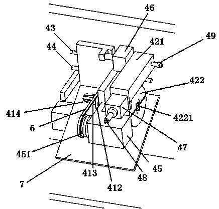
[0026] figure 1 Shown is a three-dimensional structural view of the enameled wire stripping device of Embodiment 1. The enameled wire stripping device of the present invention includes a support 2, a transmission assembly 3, a paint stripping assembly 4, a power assembly and a bracket 5, the support 2 is vertically fixed on the workbench 1, the transmission assembly 3, the paint stripping assembly 4 and the power assembly are installed on the support 2, wherein the paint stripping assembly 4 is arranged on the bracket 5 and fixed on the support 2; the power assembly includes a motor, a first cylinder 46 and the second cylinder 47 . The device uses the conveying component 3 to transmit the enameled wire to the paint stripping component 4, and the paint stripping component 4 strips the enameled wire.

[0027]The transmission assembly 3 includes a fixed shaft 31 , a transmission gear 32 , a first transmission support mechanism 33 and a second transmission support mechanism 34 ....

Embodiment 2

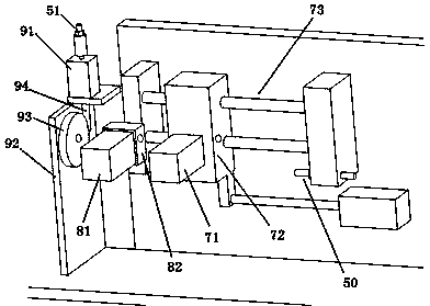
[0034] Figure 4 Shown is the three-dimensional structural view of the enameled wire stripping device of the second embodiment. The enameled wire stripping device of the present invention comprises a support 2, a transmission assembly 3, a paint stripping assembly 4, a cutting assembly, a power assembly and a bracket 5, the support 2 is vertically fixed on the workbench 1, the transmission assembly 3, the stripping assembly The paint assembly 4 , the cutting assembly and the power assembly are all mounted on the bracket 2 , wherein the paint stripping assembly 4 is arranged on the bracket 5 and fixed on the bracket 2 . The device utilizes the conveying assembly 3 to convey the enameled wire to the paint stripping assembly 4, the paint stripping assembly 4 strips the enameled wire, and the cutting assembly is used to cut the enameled wire into multiple enameled wires of equal length.

Embodiment 2

[0035] The enameled wire paint stripping device in embodiment two has the same support 2, transmission assembly 3, paint stripping assembly 4, cutting assembly, power assembly and bracket 5 with the enameled wire paint stripping device in embodiment one, the difference is that in the implementation On the basis of the enameled wire stripping device in Example 1, the cutting function and the power part to realize this function are added. For example, 4 and 5, the cutting assembly includes a delivery part 7, a fixing part 8 and a cutting part 9, and the cutting part 9, the fixing part 8, the delivery part 7, the paint stripping assembly 4 and the The transmission components 3 are installed side by side on the support 2 in sequence. The power assembly also includes a third cylinder 71, a fourth cylinder 81 and a fifth cylinder 91, respectively controlling the conveying part 7 to convey the enameled wire, controlling the fixing part 8 to stabilize the enameled wire and controlling...


PUM


Abstract

The invention provides an enameled wire varnish stripping device, and belongs to the field of machining. The enameled wire varnish stripping device comprises a support vertically fixed to a workbench, a conveying assembly, a varnish stripping assembly, a power assembly and a supporting frame for bearing the varnish stripping assembly. The conveying assembly comprises a fixing shaft, a conveying gear, a first conveying supporting mechanism and a second conveying supporting mechanism which are sequentially arranged on the support in parallel. The supporting frame which is in an L shape and the conveying assembly are arranged on the support in parallel. The conveying assembly for conveying enameled wires is connected with the varnish stripping assembly in a transmission mode. The varnish stripping assembly for controlling the varnish stripping length is driven by the power assembly to conduct varnish stripping on the enameled wires. According to another technical scheme, the enameled wire varnish stripping device comprises the support, the conveying assembly, the varnish stripping assembly, a cutting assembly, the power assembly and the supporting frame. The fully-automatic enameled wire varnish stripping device is suitable for varnish stripping of flat wires and capable of replacing manual devices or semi-automatic devices, and time and labor are saved by means of the varnish stripping process; the device is complete in function, and stable enameled wire conveying and quick and even varnish stripping or stable enameled wire conveying, quick even varnish stripping and steady integrity cutting can be completed.

Description

technical field [0001] The invention relates to the technical field of mechanical processing, in particular to an enameled wire stripping device. Background technique [0002] Enameled wire refers to the metal wire used to wind the electromagnetic coil with insulating varnish as the insulating coating, also known as the electromagnetic wire. Enameled wire is divided into round wire and flat wire according to the insulation thickness. It is the main raw material for electromagnetic windings of motors, electrical appliances, telecommunications and electronic instruments. When enameled wire is used, it is necessary to peel off the insulating varnish, and the commonly used method of stripping the varnish at present is mainly scraping and removing the varnish, which requires manual use of a knife or a knife saw to peel off the varnish. In order to avoid scratching the wire, this method is time-consuming, laborious and difficult to control the length and thickness of the scraped...

Claims


Application Information

Patent Timeline
Patent Type & Authority Applications(China)
IPC IPC(8): H01R43/28
CPCH01R43/28H01R2201/22
Inventor 施国荣沈钟铭谢杨袁力
Owner 湖州凯合电机有限公司
Why Eureka
Try Eureka