Grid Fault Partitioning Method
A technology for power grid faults and fault areas, applied in electrical components, circuit devices, AC network circuits, etc., can solve the problems of ignoring the reliability of the power grid, unable to reflect the state of the power grid, etc., and achieve the effect of preventing blackouts.
- Summary
- Abstract
- Description
- Claims
- Application Information
AI Technical Summary
Problems solved by technology
Method used
Image
Examples
example 1
[0102] Example 1: Line L 8~5 A failure occurs (considered in terms of state fragility indicators).
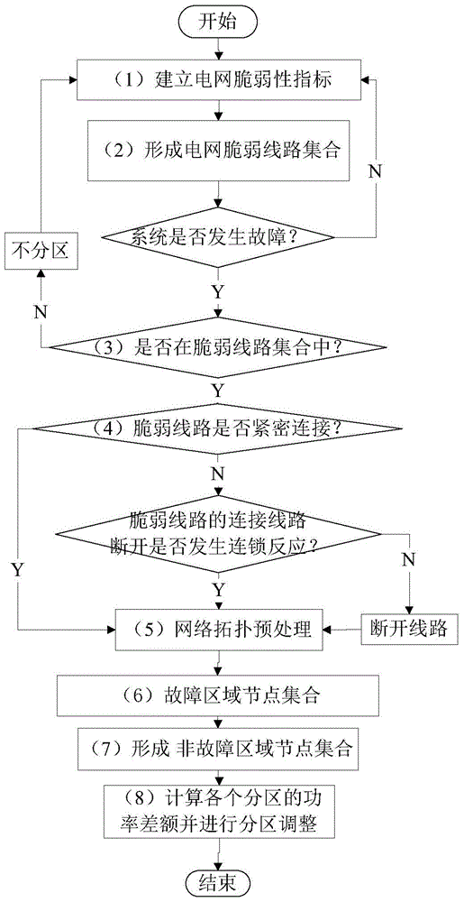
[0103] when line L 8~5 A fault occurs, and the line L in the vulnerable line set 9~10 , L 8~9 , L 8~5 , L 5~6 closely connected with the line L 30~17 via line L 8~30 connect, disconnect line L 8~30 Analysis of the system, the results show that L 8~30 The disconnection of L will not cause cascading failures in other lines, so the line L must be disconnected 8~30 . Use the method in the embodiment of the present invention to perform network topology preprocessing on the system, set N nodes in the fault area n A series of processes such as the preliminary formation of the non-fault area node set, the calculation of the power balance in each zone, and the adjustment of the zone, the zone structure diagram is obtained as follows: Figure 9 shown.
[0104] Among them, the set of partition boundary lines is [8, 30; 7, 12; 3, 12; 11, 12; 1, 2; 13, 15], and the power balance...
example 2
[0108] Example 2: Line L 34~43 A failure occurs (considered in terms of state fragility indicators).
[0109] Line L 34~43 not in a vulnerable line, when line L 34~43 When a failure occurs, the system does not have a partition phenomenon, so the output result is still the original image of the system.
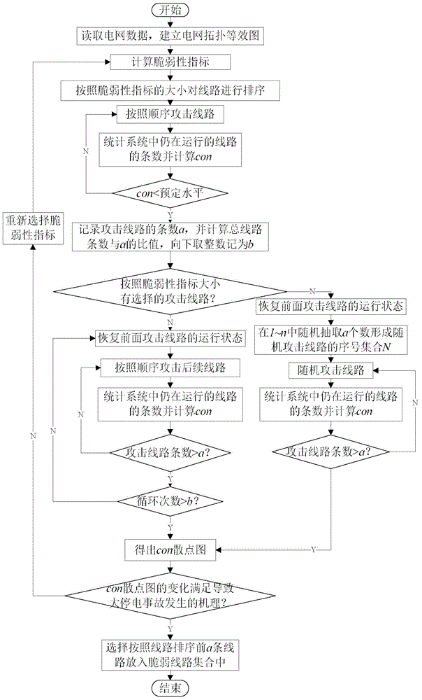
[0110] Next, the vulnerability index of the line is considered. As described in the specific embodiments of the present invention, the vulnerability index of the line includes a structural vulnerability index and a state vulnerability index. In particular, in this example, both the structural vulnerability index and the state vulnerability index have a weight of 0.5. Due to the change of the vulnerability index, the vulnerable line set of the power grid system is also correspondingly changed to [38, 65; 30, 38; 8, 5; 65, 68; 8, 9; 9, 10], that is, the vulnerable line is L 38~65 , L 30~38 , L 8~5 , L 65~68 , L 8~9 and L 9~10 .
example 3
[0111] Example 3: Line L 8~5 A fault occurs (considered by the vulnerability index of the line).
[0112] when line L 8~5 In the event of a failure, the L 38~65 , L 65~68 with L 30~38 connected, L 8~5 , L 8~9 and L 9~10 Connected, the two groups of lines are connected by line L in the middle 8~30 Connect, disconnect line L 8~30 Simulation of the system shows that L 8~30 The disconnection of L will not cause cascading failures in other lines, so the line L can be disconnected 8~30 . According to the embodiment of the present invention, the network topology preprocessing is performed on the system, and the fault area node set N n A series of processes such as the preliminary formation of the non-fault area node set, the calculation of the power balance analysis in each zone, and the zone adjustment, etc., the zone structure diagram is obtained as follows: Figure 10 shown.
[0113] Figure 10 The set of partition boundary lines in is [8, 30; 12, 14; 12, 16; 13, 15]...
PUM
 Abstract
Description
Claims
Application Information
 - R&D
- Intellectual Property
- Life Sciences
- Materials
- Tech Scout
- Unparalleled Data Quality
- Higher Quality Content
- 60% Fewer Hallucinations
Browse by: Latest US Patents, China's latest patents, Technical Efficacy Thesaurus, Application Domain, Technology Topic, Popular Technical Reports.
© 2025 PatSnap. All rights reserved.Legal|Privacy policy|Modern Slavery Act Transparency Statement|Sitemap|About US| Contact US: help@patsnap.com


