
A camera module signal wiring method

A camera module and data signal line technology, which is applied in image communication, TV, color TV, etc., can solve the problems of large difference in signal pair wiring length, camera module signal distortion, limited space area, etc., and achieve transmission rate Consistent, good anti-interference, good effect of differential impedance control

Inactive Publication Date: 2018-01-30
江西意科斯光电科技有限公司
View PDF5 Cites 0 Cited by
  • Summary
  • Abstract
  • Description
  • Claims
  • Application Information

AI Technical Summary

Problems solved by technology

At present, with the emergence of high-pixel optical sensors and mature technology (such as 8M, 13M, etc.), the use of high-end pixel sensors is becoming more and more common. Limited, it is impossible to meet the ideal wiring requirements. For example, in the past, the signal line pairs are always kept in parallel with each other, and the final signal line length difference between the signal pairs is large, which will cause signal distortion in the camera module and fail to work. and job instability

Method used


Image

  • A camera module signal wiring method
  • A camera module signal wiring method
  • A camera module signal wiring method

Examples


Embodiment 1

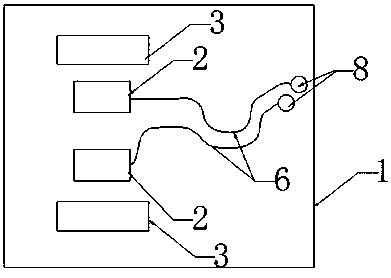
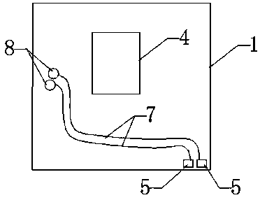
[0029] Along the data signal line, the MIPI first performs detour parallel routing on the front of a PCB board of the substrate body, and then goes around to the back of the PCB board through the through hole, and continues to detour parallel routing along the data signal line, and finally , the total trace length of the signal pair is matched.

Embodiment 2

[0031] Along the data signal line, the MIPI pair first detours parallel wiring on the front of one PCB board of the substrate body, and then goes around to the front of another adjacent PCB board through the through hole, and continues to detour along the data signal line in parallel. trace, and eventually, the total trace length for that signal pair is matched.

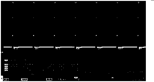
[0032] Under the condition of relatively limited design space, the present invention adopts the above-mentioned detour parallel wiring method on a multi-layer substrate with a main body size of 8.5×8.5mm, 7.5×7.5mm, or 6.5mm, which changes the previous MIPI signal Always maintain a straight line and parallel way when aligning the traces, and finally achieve the same width and spacing of the MIPI signal pair traces, and match the length of the traces to make the transmission rate consistent. (refer to image 3 , 4 , 5)

[0033] This differential signal (differential signal) pair trace length matching routing method...


PUM


Abstract

The invention discloses a camera module signal wiring method, which is implemented in the camera module signal line wiring structure. The signal line wiring structure includes: a substrate body, an optical sensor and a plurality of components, wherein the substrate body is provided with There is a wiring PAD, the optical sensor is located on the front of the substrate body, and multiple components are distributed on the front of the substrate body and located outside the optical sensor; the signal routing method includes the following steps: (1) signal detour parallel routing ; (2) smoothing. Under the condition of relatively limited design space, the present invention matches the length of the differential signal (differential signal) pair through the wiring method of the data signal line in the optical sensor, so that the transmission rate is consistent and better anti-interference performance is achieved. Higher speed, fewer signal wire connections and better differential impedance control of wire-to-signal enable the camera module to have the advantages of stable operation and strong anti-interference performance.

Description

technical field [0001] The invention relates to the field of camera module design, in particular to a signal routing method of a camera module. Background technique [0002] With the continuous improvement and update of new bus protocols, the requirements for CCM design modules are also increasing day by day. Various signals are not just purely connected and conducted, especially for MIPI signals. [0003] High-end pixel sensors basically have MIPI signal pairs above 2Lane. At present, with the emergence of high-pixel optical sensors and mature technology (such as 8M, 13M, etc.), the use of high-end pixel sensors is becoming more and more common. Limited, it is impossible to meet the ideal wiring requirements. For example, in the past, the signal line pairs are always kept in parallel with each other, and the final signal line length difference between the signal pairs is large, which will cause signal distortion in the camera module and fail to work. and job instability. ...

Claims


Application Information

Patent Timeline
Patent Type & Authority Patents(China)
IPC IPC(8): H05K1/02H05K1/18H04N5/225
CPCH05K1/0245H05K1/0274H05K1/181H05K2201/10121H05K2201/10151H04N23/50
Inventor 田风
Owner 江西意科斯光电科技有限公司
Learn More