drive train

A technology of drive system and drive shaft, applied in the field of drive system, can solve the problems of heavy, high cost, limited power, etc., and achieve the effect of compact moment of inertia

Active Publication Date: 2018-11-09
VOITH PATENT GMBH
View PDF8 Cites 0 Cited by
  • Summary
  • Abstract
  • Description
  • Claims
  • Application Information

AI Technical Summary

Problems solved by technology

[0003] The disadvantage of all these constructions is that they are usually very large and heavy
This results in enormous moments of inertia, which adversely affect the dynamics and result in high costs
Finally, they also limit the power of such drive trains

Method used


Image

  • drive train

Examples


Embodiment Construction

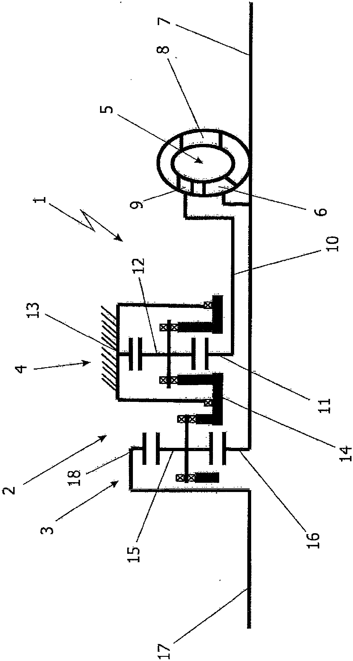
[0015] In the single figure shown, the upper half of the essentially rotationally symmetrical drive train 1 is highly schematically illustrated. This upper part is to be understood as a principle presentation for explaining the idea according to the invention. Here it is a possible embodiment in which an upstream and / or downstream mounted transmission is omitted. The drive train 1 shown basically comprises a power-split transmission 2 with a first planetary transmission 3 as a superposition transmission. Furthermore, the second planetary gear 4 configured as a planetary gear is part of the power split gear 2 of the drive train 1 according to the invention.

[0016] Another important component of the drive train 1 according to the invention is the hydrodynamic component 5 , which can form, for example, a converter, a Trilok converter or possibly also a hydrodynamic clutch. In the exemplary embodiment shown here, the hydrodynamic component 5 is designed as a hydrodynamic conve...


PUM


Abstract

The present invention relates to a drive train for transmitting variable power to a power generating device with a variable input rotational speed at the drive shaft and a substantially constant output rotational speed at the output shaft, which consists of a wind turbine or a water turbine Such a turbine drive has a power-split transmission comprising a first planetary transmission as a superposition transmission and a second planetary transmission as a planetary gear transmission, and has a hydrodynamic assembly which receives power from the output side, And this power is returned in a regulated manner to the split power transmission, the invention is characterized in that the two planetary transmissions are coupled to one another via a common planetary carrier.

Description

technical field [0001] The present invention relates to a drive train for transmitting varying power having a variable input rotational speed and a substantially constant output rotational speed. Background technique [0002] A generic drive train is known from DE 103 14 757 B3. In the drive train described there, a power split transmission combined with a hydrodynamic component is known for the regulated return of power to the power split transmission. The drive train is mainly used in the wind energy sector, but is also suitable, for example, for use with water turbines, which supply different input speeds to the input shaft of the drive train. In the drive train described in said document, the input shaft is connected to the planetary carrier of the first planetary gear. The first and second planetary gears form a power split gear, which are connected to one another via their ring gears. When the hydrodynamic unit is configured as a converter, the sun gear is connected...

Claims


Application Information

Patent Timeline
Patent Type & Authority Patents(China)
IPC IPC(8): F16H47/08F03D15/00
CPCF03D15/00F03B11/06F03B13/00F16H47/08F05B2260/40311F05B2240/53Y02E10/20Y02E10/72F03D80/70F03D15/10F16H47/085
Inventor 伯恩哈德·卢达斯曼努埃尔·拉特格布
Owner VOITH PATENT GMBH
Why Eureka
Try Eureka