Output control method of welding power supply

A technology for welding power supply and output control, which is applied to welding equipment, manufacturing tools, arc welding equipment, etc., and can solve problems such as the unstable state of the first arc 31

Active Publication Date: 2017-09-15
DAIHEN CORP
View PDF1 Cites 0 Cited by
  • Summary
  • Abstract
  • Description
  • Claims
  • Application Information

AI Technical Summary

Problems solved by technology

As a result, the generation state of the first arc 31 also becomes unstable.

Method used


Image

  • Output control method of welding power supply
  • Output control method of welding power supply
  • Output control method of welding power supply

Examples


Embodiment approach 1

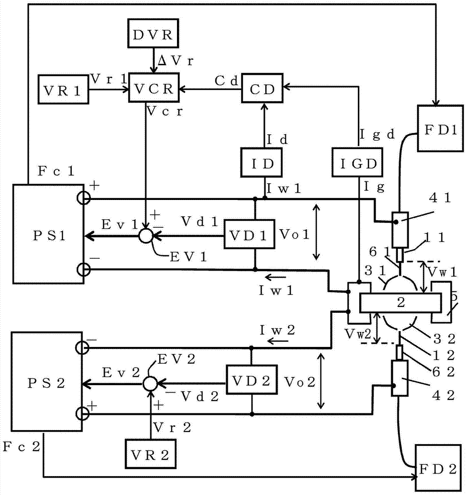
[0040] figure 1 It is a configuration diagram of a welding apparatus for simultaneously welding two welding locations of one workpiece using two welding power sources according to Embodiment 1 of the present invention. figure 1 with the above Figure 5 Correspondingly, the same symbols are assigned to the same components, and these descriptions are not repeated. exist figure 1 Among them, in order to simplify description, the invention of Embodiment 1 is implemented only about 1st welding power source PS1. Therefore, the 2nd welding power source PS2 is the same welding power source as the prior art. figure 1 exist Figure 5 A total welding current detection circuit IGD, a welding current detection circuit ID, a current energization discrimination circuit CD, a voltage increase value setting circuit DVR, and a voltage control setting circuit VCR are added. Below, refer to figure 1 , to illustrate these constituents.

[0041] The total welding current detection circuit...

Embodiment approach 2

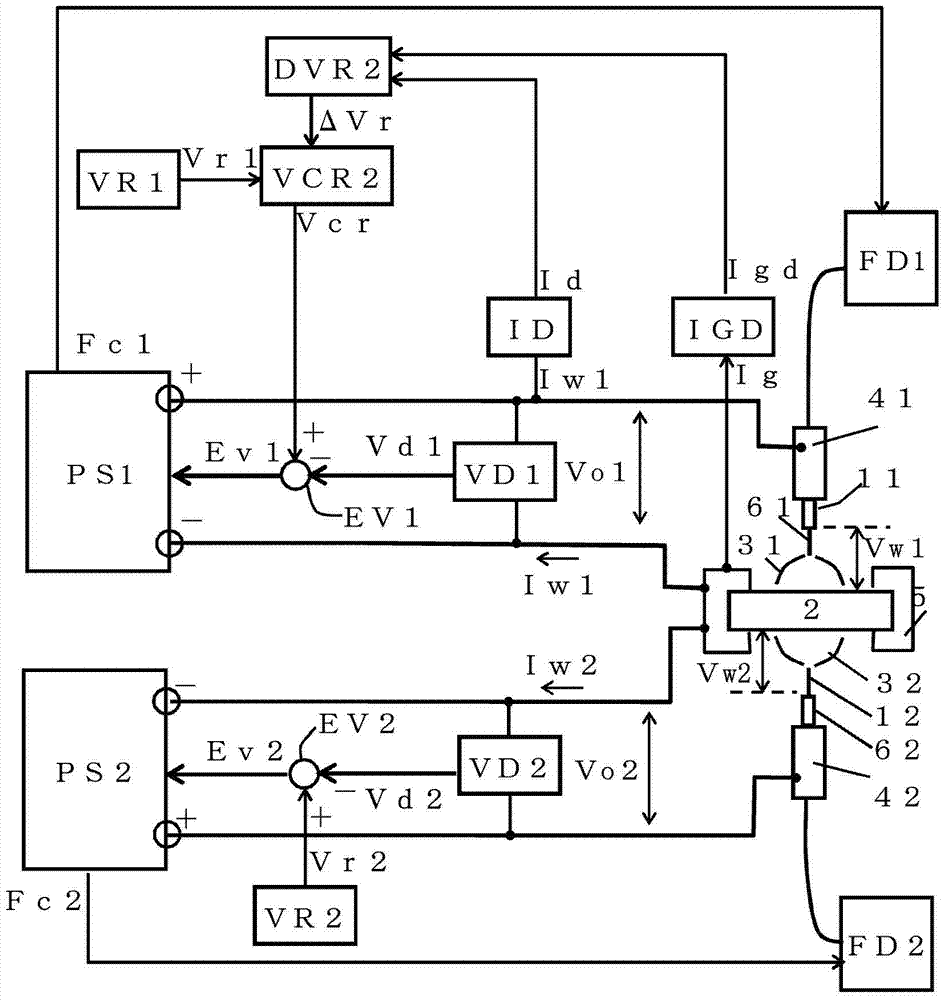
[0060] In the invention of Embodiment 1 described above, the voltage increase value is set in advance. On the other hand, in the invention of Embodiment 2, the voltage increase value is automatically set every time during welding to a value obtained by multiplying the average value of the total value of welding current energized from other welding power sources by the common resistance value. .

[0061] image 3 It is a configuration diagram of a welding apparatus for simultaneously welding two welding locations of one workpiece using two welding power sources according to Embodiment 2 of the present invention. image 3 with the above figure 1 Correspondingly, the same symbols are attached to the same components, and their descriptions are not repeated. exist image 3 Among them, in order to simplify description, the invention of Embodiment 2 is implemented only with respect to 1st welding power source PS1. Therefore, the 2nd welding power source PS2 is the same welding ...


PUM


Abstract

The invention provides an output control method for a welding power source. When a plurality of welding power sources are used at the same time, the welding power sources are prevented from being influenced by the welding currents of other welding power sources. Therefore, the welding voltage is lowered and the welding state is made unstable. The output of a welding power source (PS1) is controlled, so that the voltage detection value is equal to a voltage preset value (Vr1). In voltage detection value (Vd), according to the through power from a welding power source of the total welding current (Ig) a common energizing the electric resistance value (Rg) path and the generated voltage (Vw1)-overlapping with the welding voltage. In a common electrical path, from the other of the energized the welding power supply with the welding current is not energized, the voltage compared to a set value (Vr1) is set to increase the voltage increase (delta Vr) detecting welding power supply is energized from the other of the welding current for a total of to the mean value of the (Igd-Id), a voltage increase the value according to the delta Vr=Rg*(Igd-Id) operation are automatically set. Therefore, it is possible to suppress the reduction of the welding voltage (Vw1).

Description

technical field [0001] The present invention relates to an output control method of a welding power source in which a plurality of welding power sources respectively generate arcs on common workpieces for welding, and at least one of the power sources performs output control so that the welding voltage detection value is equal to a predetermined voltage setting value . Background technique [0002] For workpieces with multiple welding locations, sometimes multiple welding power sources are used to weld simultaneously. Hereinafter, a welding device in such a case will be described with reference to the drawings. [0003] Figure 5 It is a configuration diagram of a welding device for simultaneously welding two welding parts of one workpiece using two welding power sources. Both welding power sources are consumable electrode arc welding power sources controlled by constant voltage. Below, refer to Figure 5 Each constituent will be described. [0004] The 1st welding power...

Claims


Application Information

Patent Timeline
Patent Type & Authority Patents(China)
IPC IPC(8): B23K9/095B23K9/10
CPCB23K9/10B23K9/09B23K9/095B23K9/1043
Inventor 井手章博
Owner DAIHEN CORP
Why Eureka
Try Eureka