Plasma metal inert gas arc welding method

An arc welding method and plasma metal technology, applied in the direction of plasma welding equipment, arc welding equipment, welding equipment, etc., can solve problems such as instability and detachment, and achieve the effect of stable welding state and high-precision preheating state change

Inactive Publication Date: 2014-09-17
DAIHEN CORP
View PDF1 Cites 0 Cited by
  • Summary
  • Abstract
  • Description
  • Claims
  • Application Information

AI Technical Summary

Problems solved by technology

As a result, the droplet transfer state changes, and the droplet transfer state may deviate from the droplet transfer state once per pulse cycle and become an unstable state.

Method used


Image

  • Plasma metal inert gas arc welding method
  • Plasma metal inert gas arc welding method
  • Plasma metal inert gas arc welding method

Examples


Embodiment approach 1

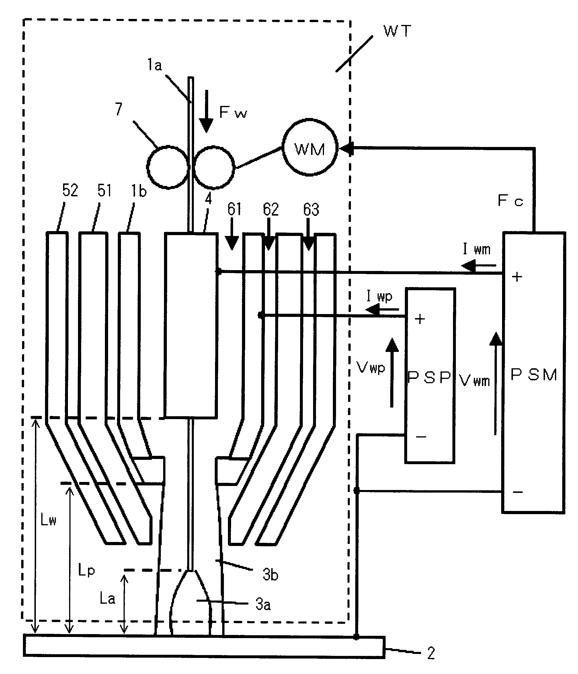
[0103] figure 1 It is a configuration diagram of a welding apparatus for carrying out the plasma metal inert gas arc welding method according to Embodiment 1 of the present invention. Hereinafter, each constituent will be described with reference to the same drawing.

[0104] This welding apparatus includes a welding torch WT surrounded by a dotted line, a metal inert gas arc welding power source PSM, and a plasma welding power source PSP. The welding torch WT has a structure in which the plasma nozzle 51 , the plasma electrode 1 b , and the power supply chip 4 are arranged concentrically within the shielding gas nozzle 52 . A shielding gas 63 such as argon or a mixed gas of argon and carbon dioxide is supplied from a gap between the shielding gas nozzle 52 and the plasma nozzle 51 . Between the plasma nozzle 51 and the plasma electrode 1b, a plasma gas 62 such as argon gas or a mixed gas of argon gas and carbon dioxide is supplied. Between the plasma electrode 1 b and the...

Embodiment approach 2

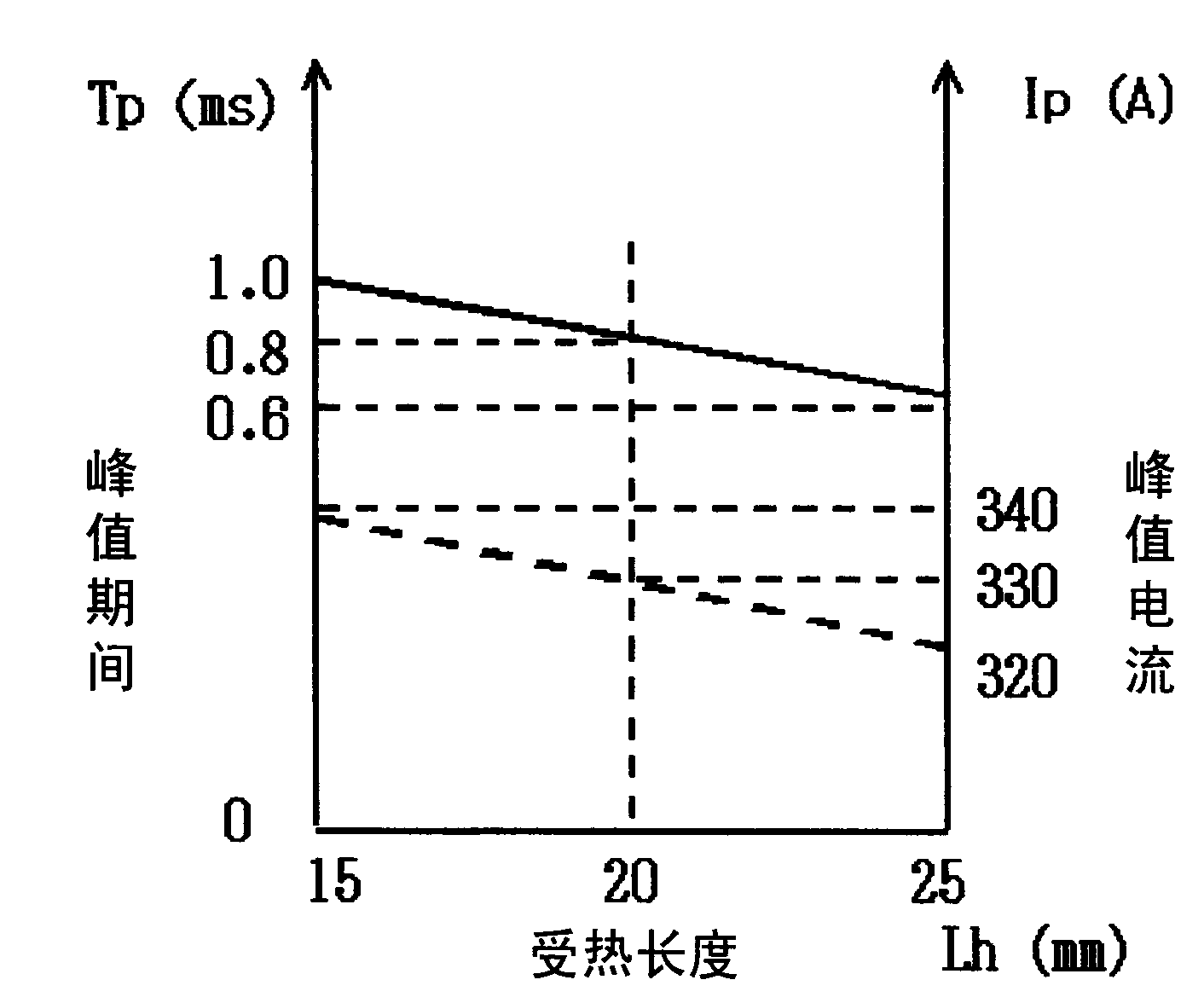
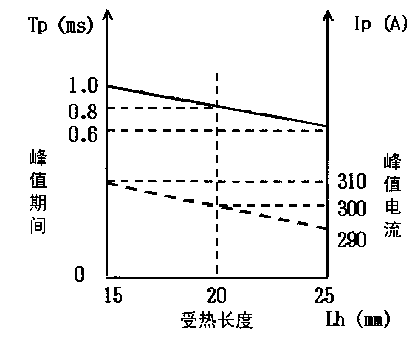
[0140] Embodiment 2 of the present invention is a case where the heated length Lh=Lp-La. Here, as described above, Lp is the distance between the tip of the plasma electrode and the base material, and La is the arc length of the metal inert gas arc. The detection method of the distance Lp between the tip of the plasma electrode and the base material is the same as that of the first embodiment. As a method of setting the arc length La, there are three methods shown below.

[0141] (1) When the arc length La is preset

[0142] An appropriate range of the arc length La for good welding is about 3 to 5 mm. Therefore, the arc length La is set to a preset constant (for example, 4 mm). In this way, although there is an error of about 1 mm from the actual arc length La, an error of this magnitude has little influence on the calculated value of the heated length Lh. If this method is used, there is an advantage that the calculation method of the heated length Lh is simple.

[0143...


PUM


Abstract

In a plasma metal insert gas arc welding method which causes a metal insert gas arc (3a) and a plasma arc (3b) to generate from a welding torch (WT), even a welding torch height (Lp) changes, a stable fused drop transition state of the metal insert gas arc can be kept. For this purpose, a plasma welding current (Iwp) is applied between a plasma electrode (1b) and a mother plate (2) for generating the plasma arc (3b). Additionally, a peak current in a peak period and a reference current in a reference period are applied between a welding wire (1a) and the mother plate (2). Furthermore, the peak period and / or the peak current is changed according to the heated length of the welding wire (1a), which is heated by the plasma arc (3b). Thus, even the welding torch height (=Lp) is changed, the unit pulse condition can be optimized correspondingly, and the stability of the fused drop transition state can be always kept.

Description

technical field [0001] The present invention relates to a plasma metal inert gas arc welding (plasma MIG welding) method, which uses a welding torch to simultaneously generate a metal inert gas (MIG: Metal Inert Gas) arc and a plasma arc to perform welding. Background technique [0002] Conventionally, a plasma metal inert gas arc welding method combining a plasma welding method and a metal inert gas arc welding method has been proposed (see, for example, Patent Document 1). In this plasma metal inert gas arc welding method, a plasma arc is generated by passing a plasma welding current between a plasma electrode arranged in a welding torch and a base material. At the same time, the plasma electrode is set in a hollow shape, and the welding wire supplied by the power supply chip (chip) arranged in the above-mentioned plasma electrode is fed through the inside of the hollow shape, and the metal is passed between the welding wire and the base material. The inert gas arc weldin...

Claims


Application Information

Patent Timeline
Patent Type & Authority Patents(China)
IPC IPC(8): B23K10/02B23K9/16B23K9/09
Inventor 小野贡平
Owner DAIHEN CORP
Why Eureka
Try Eureka