Arc welding control method
A control method and arc welding technology, applied in arc welding equipment, welding equipment, manufacturing tools, etc., can solve problems such as unstable welding state
- Summary
- Abstract
- Description
- Claims
- Application Information
AI Technical Summary
Problems solved by technology
Method used
Image
Examples
Embodiment approach 1
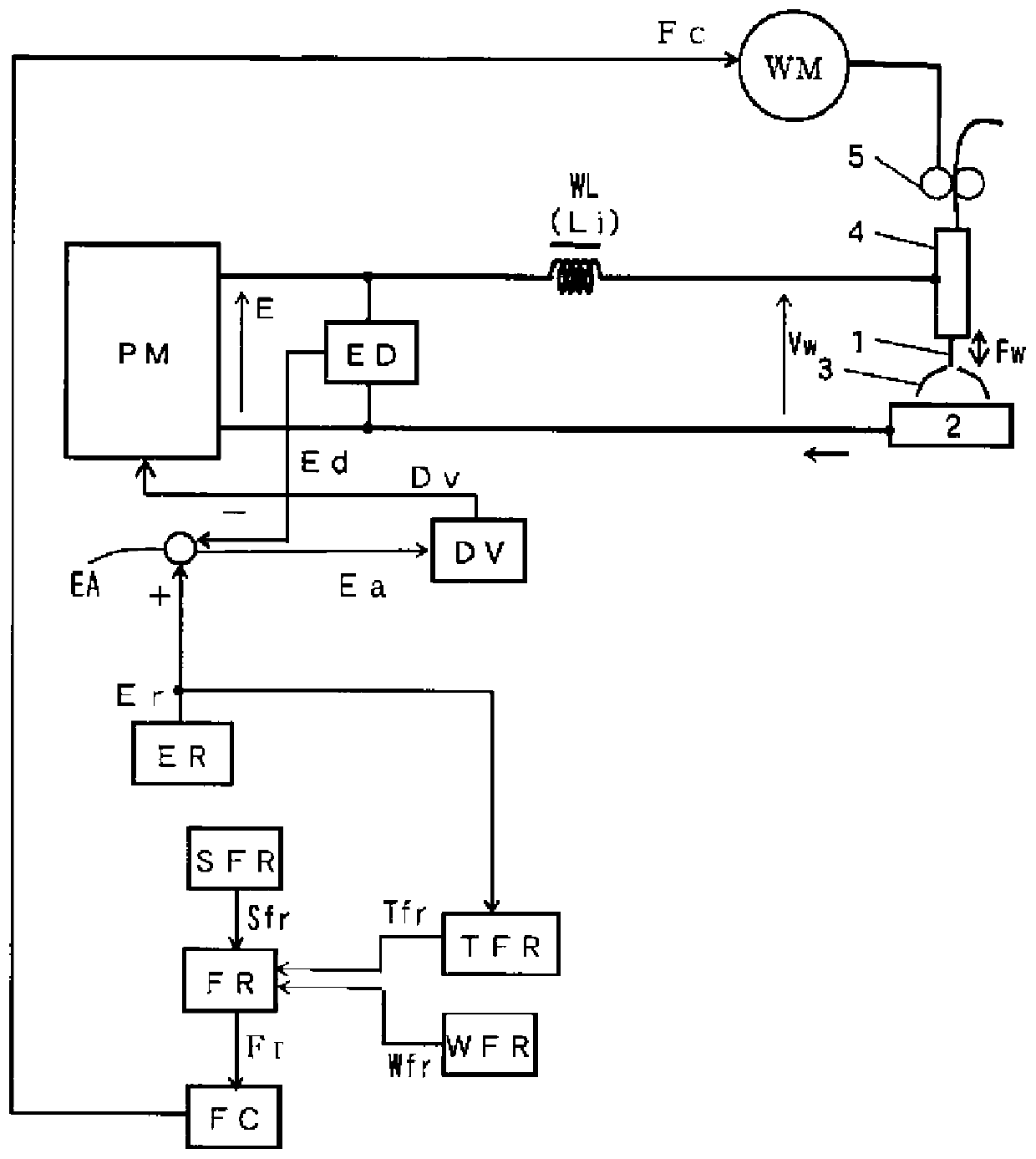
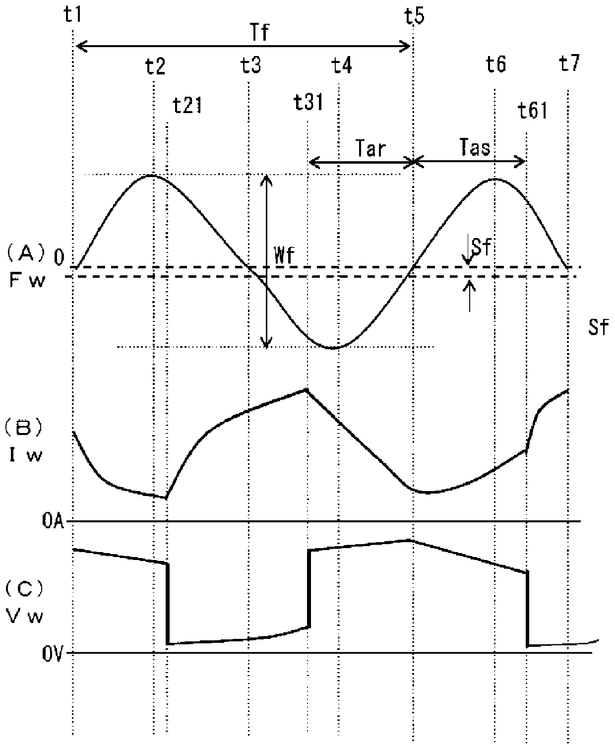
[0029] The invention of Embodiment 1 changes the cycle of the feed speed by changing the cycle of the feed speed based on the voltage setting value, thereby changing the cycle of the feed speed.
[0030] figure 1 It is a block diagram of a welding power source for implementing the arc welding control method according to Embodiment 1 of the present invention. The following reference figure 1 to illustrate the blocks.
[0031] The power supply main circuit PM receives a commercial power supply (not shown) such as 3-phase 200V as input, performs output control by inverter control or the like in accordance with a drive signal Dv described later, and outputs an output voltage E. Although not shown in the figure, this power supply main circuit PM includes: a primary rectifier for rectifying commercial power; a smoothing capacitor for smoothing rectified direct current; and the aforementioned drive signal for converting smoothed direct current into high-frequency alternating curren...
Embodiment approach 2
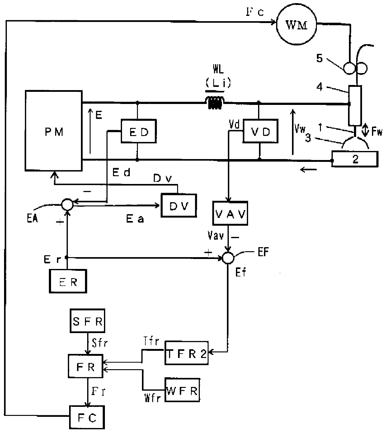
[0054] The invention of Embodiment 2 detects the smooth value of the welding voltage, and performs feedback control on the cycle of the feed speed so that the smooth value of the welding voltage becomes equal to the voltage setting value.
[0055] image 3 It is a block diagram of a welding power source for implementing the arc welding control method according to Embodiment 2 of the present invention. image 3 with the above figure 1 Correspondingly, the same squares are marked with the same labels, and their descriptions are not repeated. image 3 The voltage detection circuit VD, the voltage smoothing circuit VAV and the feed error amplifier circuit EF are added, and the figure 1 The cycle setting circuit TFR of the previous cycle is replaced by a second cycle setting circuit TFR2. The following reference image 3 to illustrate these blocks.
[0056] The voltage detection circuit VD detects the welding voltage Vw and outputs a voltage detection signal Vd. The voltage s...
Embodiment approach 3
[0062] In the invention of Embodiment 3, when the waveform of the feed speed is a trapezoidal wave, the period is changed by changing the waveform parameter of the feed speed based on the voltage setting value.
[0063] Figure 4 It is a block diagram of a welding power source for implementing the arc welding control method according to Embodiment 3 of the present invention. Figure 4 with the above figure 1 Correspondingly, the same squares are marked with the same labels, and their descriptions are not repeated. Figure 4 deleted figure 1 The cycle setting circuit TFR, the amplitude setting circuit WFR and the positive feed side displacement setting circuit SFR. And the forward feed acceleration period setting circuit TSUR, the forward feed deceleration period setting circuit TSDR, the reverse feed acceleration period setting circuit TRUR, the reverse feed deceleration period setting circuit TRDR, the forward feed To the amplitude setting circuit WSR, the reverse feed am...
PUM
 Abstract
Description
Claims
Application Information
 - R&D
- Intellectual Property
- Life Sciences
- Materials
- Tech Scout
- Unparalleled Data Quality
- Higher Quality Content
- 60% Fewer Hallucinations
Browse by: Latest US Patents, China's latest patents, Technical Efficacy Thesaurus, Application Domain, Technology Topic, Popular Technical Reports.
© 2025 PatSnap. All rights reserved.Legal|Privacy policy|Modern Slavery Act Transparency Statement|Sitemap|About US| Contact US: help@patsnap.com


