
Consumable electrode arc welding control method

A technology of arc welding and control method, which is applied in the direction of arc welding equipment, welding equipment, manufacturing tools, etc., which can solve the problems of interference, difficulty in solving welding torch and base metal, etc., and achieve the effect of suppressing the change of penetration depth

Active Publication Date: 2016-01-20
DAIHEN CORP
View PDF6 Cites 0 Cited by
  • Summary
  • Abstract
  • Description
  • Claims
  • Application Information

AI Technical Summary

Problems solved by technology

However, in deep groove welding, multi-pass welding (multiple If the distance between the power supply chip and the base metal is kept at a fixed value, it may also be difficult to solve the problem of interference between the welding torch and the base metal, etc.

Method used


Image

  • Consumable electrode arc welding control method
  • Consumable electrode arc welding control method
  • Consumable electrode arc welding control method

Examples


Embodiment approach 1

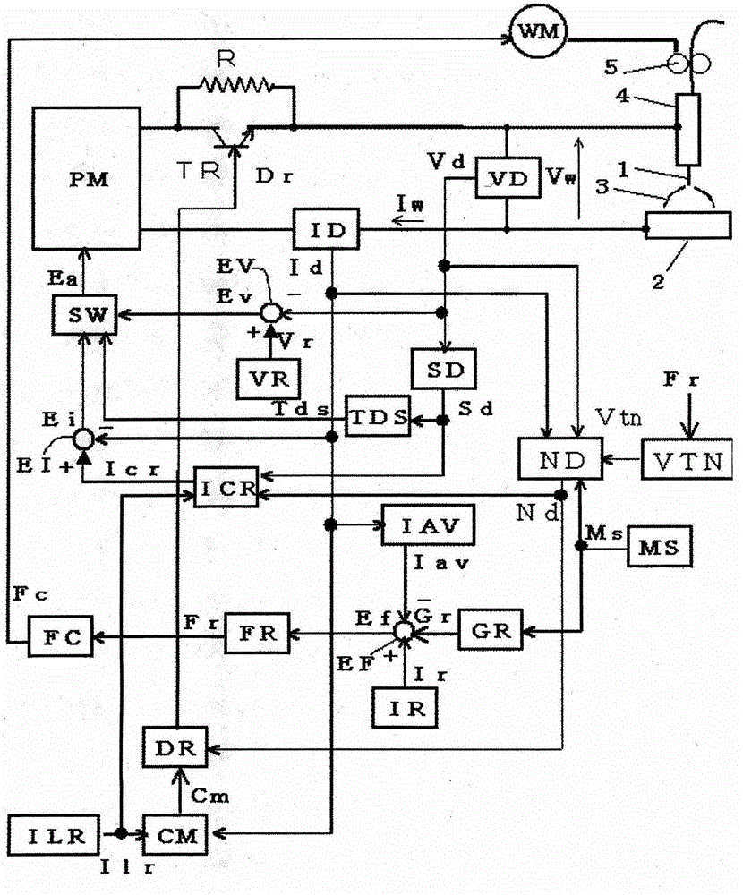
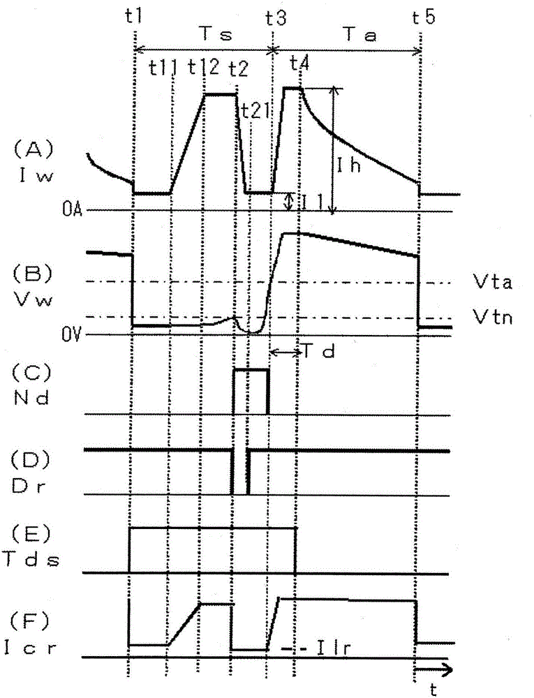
[0025] figure 1 It is a block diagram of a welding power source for implementing the consumable electrode arc welding control method according to Embodiment 1 of the present invention. Hereinafter, each block will be described with reference to this figure.

[0026] The power supply main circuit PM receives a commercial power supply (not shown) such as 3-phase 200V as input, performs output control such as inverter control according to an error amplifier signal Ea described later, and outputs welding voltage Vw and welding current Iw. Although not shown in the figure, this power supply main circuit PM includes a primary rectifier for rectifying commercial power, a smoothing capacitor for smoothing rectified direct current, and an inverter circuit for converting smoothed direct current into high-frequency alternating current. , the high-frequency transformer that steps down the high-frequency AC to a voltage suitable for welding, the secondary rectifier that rectifies the high...

Embodiment approach 2

[0073] Invention of Embodiment 2 In the invention of Embodiment 1, the number of short circuits per unit time is detected, and the operation mode selection signal Ms is switched based on the detection value of the number of short circuits. Hereinafter, the invention of Embodiment 2 will be described with reference to the drawings.

[0074] Figure 6 It is a block diagram of a welding power source for implementing the consumable electrode arc welding control method according to Embodiment 2 of the present invention. This figure is similar to the above figure 1 Correspondingly, the same symbols are assigned to the same blocks, and descriptions of these blocks are omitted. The graph is in figure 1 A short-circuit times detection circuit NS is added to the figure 1 The figure obtained after replacing the operation mode selection circuit MS of 1 with the second operation mode selection circuit MS2. Hereinafter, these blocks will be described with reference to this figure.

[...


PUM


Abstract

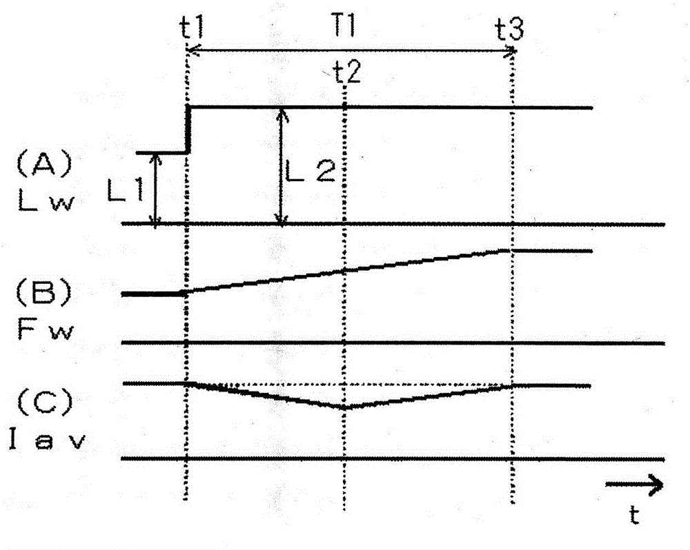
The invention provides a control method for consumable electrode arc welding. If constriction of molten droplet is detected, a welding current powered to a short circuit load is reduced so as to generate a constriction detection and control of the arc again. A feedback control (feed speed variable control) for the feed speed (Fw) is carried out according to a manner of a welding current smoothed value (Iav) equal to a predetermined current set value, so as to weld. The control method comprises an action mode for acting the constriction detection control and a forbidden mode for forbidding the constriction detection control. A transition response time (T1) of the feedback control in the action mode is longer than that in the forbidden mode. Therefore, the feed speed (Fw) changes slowly in relative to the change of a distance between a power chip and a base material, thereby keeping the welding state stably. The method can inhibit that the welding state becomes unstable when the constriction detection control acts together with the feed speed variable control at a constant welding current.

Description

technical field [0001] The present invention relates to necking detection control for reducing the welding current to regenerate the arc if droplet necking is detected, and variable feed speed control for controlling the feed speed so that the welding current is equal to a set value, thereby performing Consumable electrode arc welding control method for welding. Background technique [0002] In the invention of Patent Document 1, in the consumable electrode arc welding in which the arc generation state and the short circuit state are repeated between the welding wire and the base material, the necking detection criterion is achieved by the change of the voltage value or the resistance value between the welding wire and the base material value, to detect the precursory phenomenon of arc re-generating from the short-circuit state, that is, the necking of the droplet. If the necking is detected, the output control is: the welding current energized to the short-circuit load is r...

Claims


Application Information

Patent Timeline
Patent Type & Authority Patents(China)
IPC IPC(8): B23K9/095
Inventor 高田贤人
Owner DAIHEN CORP
Learn More