Manual pipe clamp

A pipe clamp and clamping device technology, applied in clamping, manufacturing tools, workpiece clamping devices, etc., can solve the problems of operator's personal safety hazards, large force, damage to items, etc., and achieve less danger, improved safety, energy saving effect

Inactive Publication Date: 2015-01-14
湖州华宁金属材料有限公司
View PDF5 Cites 10 Cited by
  • Summary
  • Abstract
  • Description
  • Claims
  • Application Information

AI Technical Summary

Problems solved by technology

However, since this kind of clamp is powered by electricity and an air pump, its strength is very strong, and it is easy to damage the item to be clamped
Improper operation will also cause harm to the personal safety of the operator.

Method used


Image

  • Manual pipe clamp
  • Manual pipe clamp
  • Manual pipe clamp

Examples


Embodiment 2

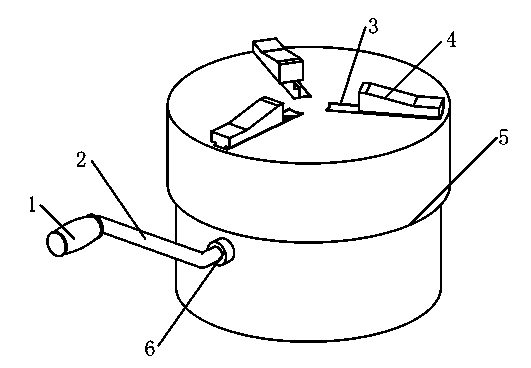
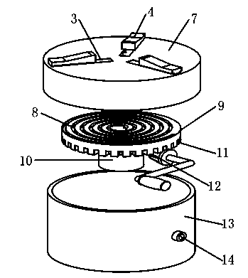
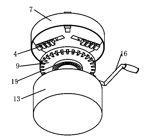
[0021] Embodiment 2: as figure 1 , figure 2 and image 3 As shown, a manual pipe clamp, housing 5, clamping device 4, compass 9 and rocker 2, housing 5 is composed of upper housing 7 and lower housing 13, upper housing 7 is installed on the lower housing 13, compass 9 is fixed on the lower shell 13, the upper shell 7 is provided with a clamping track 3, the clamping device 4 is arranged on the clamping track 3, the number of the clamping track 3 is greater than or equal to 3, and the clamping track 3 is arranged radially On the upper casing 7, the upper surface of the compass 9 is provided with a spiral track 8, the spiral track 8 is in the shape of an Archimedes spiral, and the lower end of the clamping device 4 is provided with a protrusion 16, and the protrusion 16 is engaged on the spiral track 8, the lower surface of the compass 9 is provided with a gear pattern 11, the rocker 2 is installed on the lower housing 13, and one end of the rocker 2 is provided with a bevel ...


PUM


Abstract

The invention discloses a manual pipe clamp, comprising a housing, clamping devices, a compass and a rocking bar, wherein the housing is composed of an upper shell and a lower shell; the upper shell is arranged on the lower shell; the compass is fixed on the lower shell; the upper shell is provided with three or more clamping tracks; the clamping devices are arranged on the clamping tracks; the clamping tracks are arranged on the upper shell in a radial manner; the upper surface of the compass is provided with a spiral track which is in the shape of an Archimedean spiral; a convex position is arranged at the lower end of each clamping device, and is clamped in the corresponding spiral track; gear lines are arranged on the lower surface of the compass; the rocking bar is arranged on the lower shell; and a bevel gear is arranged at one end of the rocking bar, and is meshed with the gear lines of the compass. The manual pipe clamp is provided with power by a manual operation, and gets rid of limits of power and an air compressor pump. Therefore, the manual pipe clamp is high in operability, and is less prone to a risk, the safety is greatly improved, an energy source is saved, and the manual pipe clamp is very suitable for small enterprises or processing workshops.

Description

[0001] technical field [0002] The present invention relates to a clamp, in particular to a clamp for clamping tubular or rod-shaped steel. The clamp does not provide power with electric power and air pump, and can firmly clamp the tubular or rod-shaped steel by hand. Background technique [0003] The device used to fix the processing object in the process of mechanical manufacturing so that it occupies the correct position to accept construction or inspection is called a fixture. In a broad sense, any process in the process, the device used to install the workpiece quickly, conveniently and safely, can be called a fixture. Such as welding fixtures, inspection fixtures, assembly fixtures, machine tool fixtures, etc. At present, common clamps for clamping tubular or bar-shaped steel are powered by electricity and air pumps, such as tire presses. However, since this kind of clamp is powered by electricity and an air pump, its strength is very large, and it is easy to damage...

Claims


Application Information

Patent Timeline
Patent Type & Authority Applications(China)
IPC IPC(8): B25B11/00B23Q3/00
CPCB25B11/00B23B31/16083
Inventor 邱云娟
Owner 湖州华宁金属材料有限公司
Why Eureka
Try Eureka