
Pressure-superposed water supply pumping station

A technology of water pumps and pumping stations, which is applied in the field of superimposed water supply pumping stations with water tanks, which can solve problems such as difficult control methods, poor energy saving effects, and large water pressure fluctuations

Inactive Publication Date: 2015-01-14
SHANGHAI PANDA MACHINEGRP CO LTD
View PDF6 Cites 2 Cited by
  • Summary
  • Abstract
  • Description
  • Claims
  • Application Information

AI Technical Summary

Problems solved by technology

[0002] In the prior art, there are generally two structural modes for the superimposed water supply pump station with water tank replenishment. One is to install a small booster pump at the outlet of the water tank and connect the superimposed pump in series to solve the problem of pressurizing the water in the water tank when the tap water is insufficient. Until the tap water pressure meets the flow requirements of the stack pump, the head of the stack pump can be reduced by subtracting the tap water pressure to reduce the power, but the disadvantages of this method are high manufacturing cost, high installation strength, difficult control methods, and large water pressure fluctuations
Another way is not to configure a booster pump, the power of the stacked pump is increased according to the full head configuration, and when the tap water pressure is insufficient, the stacked pump is switched to the water tank to absorb water. This way can reduce the configuration of the booster pump, but the water pump will run In two working conditions (water inlet with pressure and no pressure), the energy saving effect of the pump is not as good as the first one when it is running

Method used


Image

  • Pressure-superposed water supply pumping station

Examples


Embodiment Construction

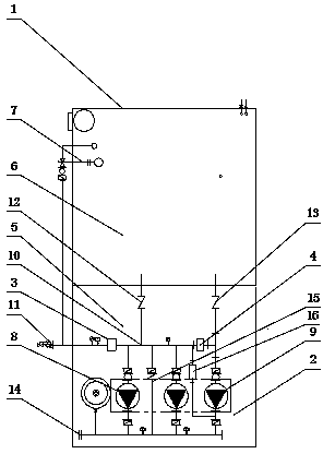
[0007] Such as figure 1 A stacked feedwater pumping station shown includes: shell 1, water pump unit 2, tap water protection device 3, normally open solenoid valve 4, normally closed solenoid valve 16, control cabinet (not marked in the figure) and valves. Body 1 is divided into equipment room 5 and water storage room 6, tap water is connected to water storage room 6 through float valve 7, water pump unit 2 is divided into stack pump 8 and booster stack pump 9, tap water protection device 3 adopts hydraulic control, The higher the tap water pressure is, the larger the opening is and the more the excess flow is. The water inlet of the stack pump 8 is connected to the water inlet pipe 10, the water outlet of the stack pump 8 is connected to the water outlet pipe 14, and the inlet of the booster stack pump 9 passes through. The normally open solenoid valve 4 is connected to the water inlet main pipe 10, the inlet of the booster stack pump 9 is connected to the water storage room ...


PUM


Abstract

The invention relates to a pressure-superposed water supply pumping station. When equipment works, a tap water protecting device is hydraulically controlled, so that the higher the pressure of tap water, the greater the degree of opening, and the more the excess flow; when the pressure of tap water is normal, the tap water protecting device is automatically turned on, a water pumping set operates at variable frequencies to carry out the superposed pressure boosting to supply water to users, accordingly, each pump in the water pumping set can perform the superposed pressure boosting water supply on the pressure basis of the tap water to achieve the energy saving purpose. When the tap water pressure is reduced and flow cannot meet the use requirement of users, the degree of opening of the tap water protecting device is reduced to protect the pressure of tap water from being continuously reduced; meanwhile, a system controls a normally open solenoid valve to turn off and a normally closed solenoid valve to turn on, a pressure boosting superposed pump changes to pump water from a water tank, and the water outflowing pressure of the pressure boosting superposed pump is automatically adjusted, so that the water outflowing pressure and the tap water pressure are matched, storing water in the water tank is pumped by the pressure boosting superposed pump to a water inlet manifold through the normally closed solenoid valve, and the superposed pump is enabled to be simultaneously supplied by the tap water and the storing water from the water tank, and thus water use requirements of the users are met and simultaneously the tap water is enabled to not generate negative pressure.

Description

technical field [0001] The invention relates to a water supply pump station, in particular to a superimposed water supply pump station with a water tank. Background technique [0002] In the prior art, there are generally two structural modes for the superimposed water supply pump station with water tank replenishment. One is to install a small booster pump at the outlet of the water tank and connect the superimposed pump in series to solve the problem of pressurizing the water in the water tank when the tap water is insufficient. Until the tap water pressure meets the flow requirements of the stack pump, the lift of the stack pump can be reduced by subtracting the tap water pressure to reduce the power. However, the disadvantages of this method are high manufacturing cost, high installation strength, difficult control methods, and large water pressure fluctuations. Another way is not to configure a booster pump, the power of the stacked pump is increased according to the fu...

Claims


Application Information

Patent Timeline
IPC IPC(8): E03B5/02
CPCE03B5/02
Inventor 池学聪谭红全
Owner SHANGHAI PANDA MACHINEGRP CO LTD
Learn More