Flow control sleeve cylinder set

A technology of flow control and sleeve group, which is applied in the direction of sliding valves, engine components, mechanical equipment, etc., and can solve problems such as difficult construction, failure to function, and high cost

Inactive Publication Date: 2015-01-14
METAL INDS RES & DEV CENT
View PDF7 Cites 9 Cited by
  • Summary
  • Abstract
  • Description
  • Claims
  • Application Information

AI Technical Summary

Problems solved by technology

[0002] The valve body is the most popular mechanical device used to control fluid delivery. It is mainly used in fluid delivery systems. The valve body is installed in the pipeline between the fluid supply end and the use end to change the fluid flow direction and guide The functions of fluid forming shunt, adjusting fluid velocity and flow rate, cutting off fluid circulation, etc.; and when the fluid delivery system needs to change the flow of fluid in the pipeline, such as the existing 18-inch control valve assembled on the pipeline, and according to the use requirements To reduce the flow rate to four inches or less, according to the current technology, it is usually to replace a new set of flow characteristic control valves or add another four-inch pipeline and valve to meet the needs of use, but these two methods are not only difficult to construct , and need to replace or add many parts at the same time, resulting in high cost, so it is a problem that still needs to be improved
[0003] In order to improve the effect of flow regulation, the valve body can be further improved. A single-layer sleeve is provided at the valve core, and the flow is adjusted through the perforation opened on the sleeve. However, the valve body with this structure only The fixed flow coefficient can be adjusted. When the system wants to change the flow characteristics, it is still only possible to choose to replace a new set of valve bodies or add new pipelines, which cannot effectively improve the problem
[0004] Another example is the Chinese Taiwan Announcement No. M419846 New Patent "Improved Structure of Cage Valve" proposed earlier by the applicant of the present invention, which controls the flow of fluid through the structure of a three-layer cage sleeve, allowing users to adjust the flow of fluid according to their needs. The number of perforations is used to achieve the function of regulating the flow; however, in the structure of this case, because the cage moves up and down through the rotating shaft, a relatively deep space is required to unfold the three-layer cage. In actual use, the space in the general valve body is difficult to meet the needs of use, and cannot play a complete role; moreover, the position of the perforation of each layer of the cage sleeve in this case must also meet a certain corresponding relationship, so that the cage When the set is not unfolded, the perforations of each layer can be matched for fluid circulation, which is also inconvenient in production and use

Method used


Image

  • Flow control sleeve cylinder set
  • Flow control sleeve cylinder set
  • Flow control sleeve cylinder set

Examples


Embodiment Construction

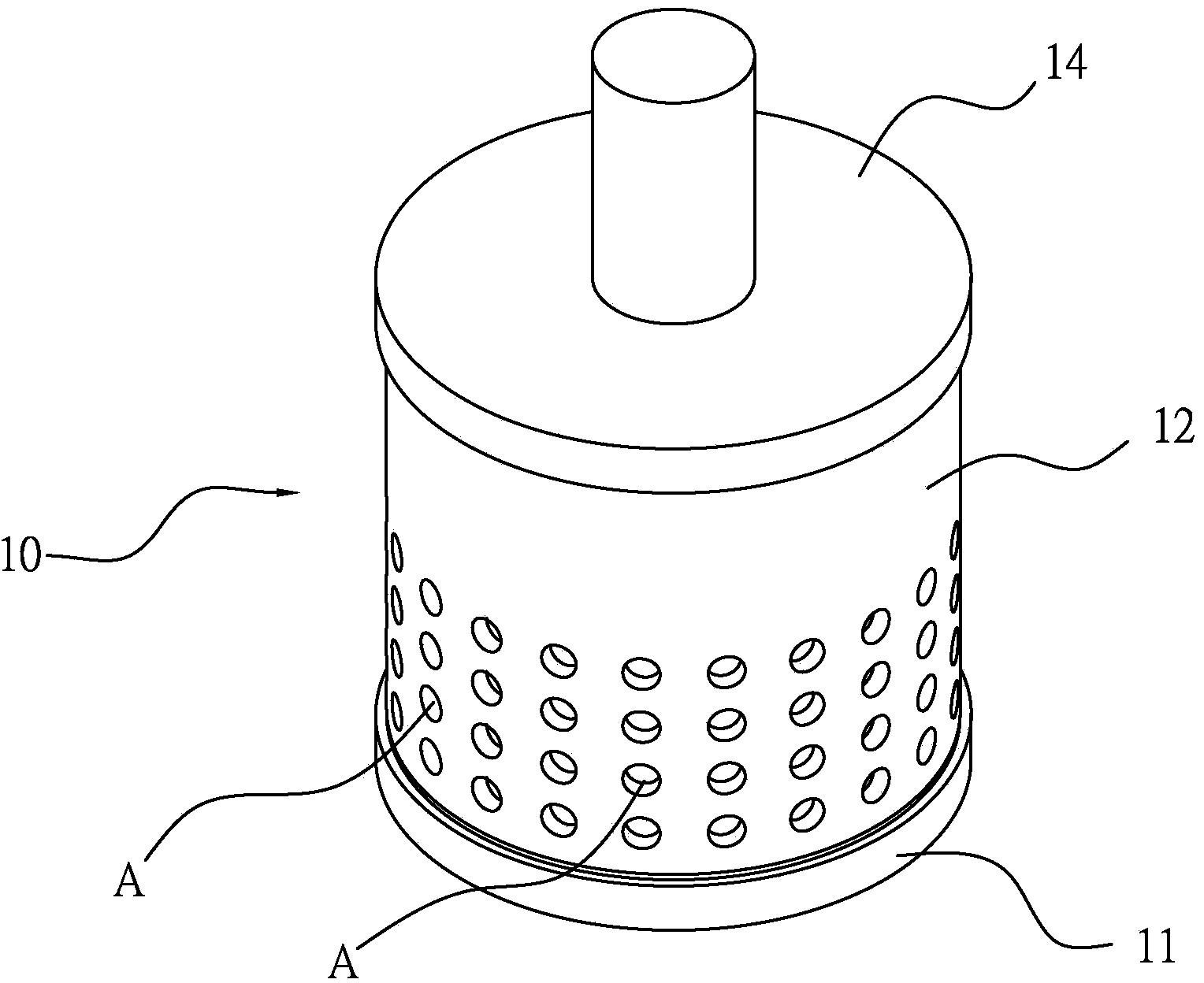
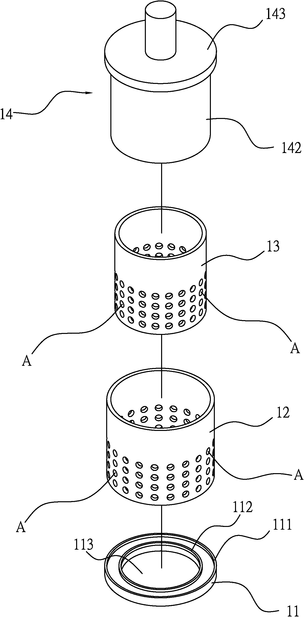
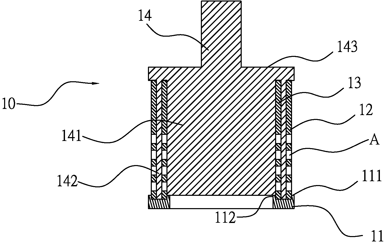
[0032] see figure 1 and figure 2 , is a schematic diagram of the appearance of the flow control sleeve set in the best embodiment of the present invention and an exploded view of components. As shown in the figure, the main structure of the flow control sleeve set 10 of this embodiment includes a base 11, a first sleeve 12, a The second sleeve 13 and a valve plug 14 .

[0033] In this embodiment, the base 11 is located at the bottom of the flow control sleeve set 10, and its appearance is roughly circular, that is, a through flow channel 113 is formed in the middle of the base 11, and the outer edge and the inner surface of the upper surface of the base 11 A first flange 111 and a second flange 112 respectively protrude upward from the edge, respectively used for positioning the first sleeve 12 and the second sleeve 13 combined on the base.

[0034] The first sleeve 12 and the second sleeve 13 are both hollow cylinders, and are respectively provided with at least two perfor...


PUM


Abstract

The invention relates to a flow control sleeve cylinder set which mainly comprises a base, a first sleeve cylinder, a second sleeve cylinder and a valve piston wherein the base is arranged at one channel of a valve body and is located between the inlet end and the outlet end of the channel. The first sleeve cylinder is located at the inner side of the second sleeve cylinder. Both the first sleeve cylinder and the second sleeve cylinder are provided at least two through holes. The through holes are arranged on the base at appropriate distance from each other. The top end of the valve piston is connected with one driving shaft of the valve body and can move upwardly or downwardly to the driving shaft so as to control the number of through holes to be communicated of the first sleeve cylinder and the second sleeve cylinder. For the structure provided by the invention, not only a two layer sleeve cylinder structure is provided to prevent interfering flow and to achieve best effect of flows. In addition, for the free change and arrangement of sleeve cylinders, the pipelines of liquid equipment can correspond to requirement of flow characteristics. Capable of being conveniently adopted to various valves, the convenience of the application of the invention can be increased.

Description

technical field [0001] The invention relates to a flow control assembly applied to a valve body, in particular to a flow control sleeve set with double-layer porous sleeves. Background technique [0002] The valve body is the most popular mechanical device used to control fluid delivery. It is mainly used in fluid delivery systems. The valve body is installed in the pipeline between the fluid supply end and the use end to change the fluid flow direction and guide The functions of fluid forming shunt, adjusting fluid velocity and flow rate, cutting off fluid circulation, etc.; and when the fluid delivery system needs to change the flow of fluid in the pipeline, such as the existing 18-inch control valve assembled on the pipeline, and according to the use requirements To reduce the flow rate to four inches or less, according to the current technology, it is usually to replace a new set of flow characteristic control valves or add another four-inch pipeline and valve to meet th...

Claims


Application Information

Patent Timeline
Patent Type & Authority Applications(China)
IPC IPC(8): F16K3/26F16K3/314F16K3/32
CPCF16K3/262F16K3/265F16K3/314F16K3/32
Inventor 曾博义郑远中谢运金林清安
Owner METAL INDS RES & DEV CENT
Why Eureka
Try Eureka