Electromagnetic gun bullet and rail gun

A shell and electromagnetic technology, applied in the field of shells, can solve problems such as increased friction, guide rail ablation, and maximum current limitation, and achieve the effects of enhanced contact performance, simple structure, and high initial firing speed

Inactive Publication Date: 2015-01-14
BEIJING DINGLIANG TECH
View PDF3 Cites 6 Cited by
  • Summary
  • Abstract
  • Description
  • Claims
  • Application Information

AI Technical Summary

Problems solved by technology

And when the metal conductor with larger area is adopted, the weight of the electromagnetic gun projectile is increased, which in turn causes the launch velocity of the electromagnetic gun projectile to be reduced.
In addition, when rigid metal materials are used, the two sides of the projectile armature are in poor contact with the guide rail. Even if there is a small contact resistance, when a large current flows, it is very easy to cause ablation of the guide rail; When both sides of the pivot are in too close contact with the guide rail, the friction force will be significantly increased. When the projectile is in the firing state, the maximum current flowing through the metal projectile is limited.
It can be seen that the electromagnetic gun projectiles using metal materials restrict the launch speed of the electromagnetic gun projectiles, and it is impossible to obtain high-speed electromagnetic gun projectiles.

Method used


Image

  • Electromagnetic gun bullet and rail gun
  • Electromagnetic gun bullet and rail gun
  • Electromagnetic gun bullet and rail gun

Examples


Embodiment Construction

[0018] The present invention is described in detail below in conjunction with accompanying drawing:

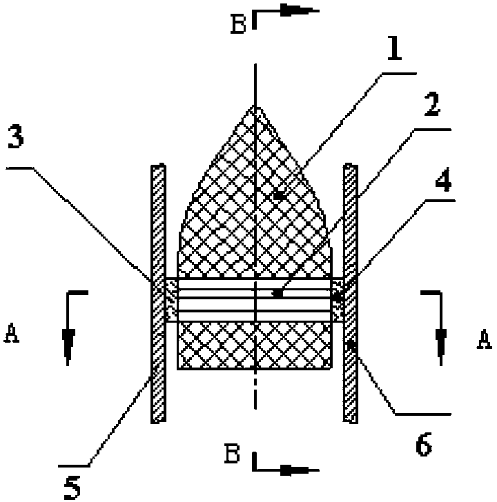
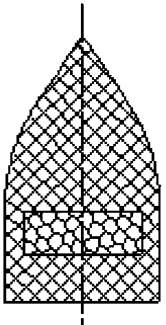
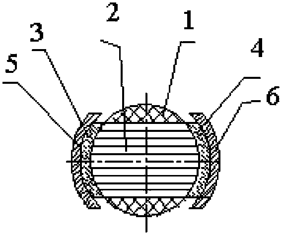
[0019] like Figure 1-3 As shown, the present invention provides an electromagnetic gun projectile, including a projectile body and an armature; the armature includes an armature body, a left carbon brush and a right carbon brush; the left carbon brush is glued to the left end of the armature body Then, the right carbon brush is bonded to the right end of the armature body; the armature body is bonded to the projectile body; the armature body is a non-metallic fiber conductor. The armature body and the projectile body are bonded by thermosetting resin. or other bonding materials. The fiber conductor of non-metallic material is composed of a group of non-metallic fibers arranged in parallel or non-parallel in the same direction.

[0020] It should be noted that in the present invention, the non-metallic fiber used for the armature body can be an existing non-metallic fiber, ...


PUM


Abstract

The invention provides an electromagnetic gun bullet and a rail gun. The electromagnetic gun bullet comprises a bullet body and an armature. The armature comprises an armature body, a left carbon brush and a right carbon brush. The left carbon brush adheres to the left end of the armature body, and the right carbon brush adheres to the right end of the armature body adhering to the bullet body. The armature body is a non-metal material fiber conductor. Because the armature body is the non-metal material fiber conductor, fiber material has certain elasticity, under the action of pressure, the contact performance between the carbon brushes at the two ends of the armature and guide rails can be improved, and in the process of driving the electromagnetic gun bullet, a good movement state can be guaranteed. On the other hand, because the fiber conductor is high in electric conductivity and large in current-carrying capacity, under the same electric conduction area, larger current can pass to generate larger Lorentz force to drive the electromagnetic gun bullet, so that the electromagnetic gun bullet is higher in initial shooting speed and has the advantage of being simple in structure.

Description

technical field [0001] The invention relates to a projectile for a cannon, in particular to a projectile for an electromagnetic cannon and a railgun. Background technique [0002] The launch principle of the electromagnetic gun projectile is: the electromagnetic gun projectile passes through an electric current, thereby generating a Lorentz force, and drives the electromagnetic gun projectile to be launched under the action of the Lorentz force. Therefore, the launch speed of the electromagnetic gun projectile is mainly restricted by two conditions: the weight of the electromagnetic gun projectile itself and the magnitude of the current passed by the electromagnetic gun projectile. That is: the greater the current passing through the electromagnetic gun projectile, the lighter the weight of the electromagnetic gun projectile itself, and the greater the launch speed of the electromagnetic gun projectile. [0003] At present, the structure of the electromagnetic gun projectil...

Claims


Application Information

Patent Timeline
Patent Type & Authority Applications(China)
IPC IPC(8): F41B6/00
Inventor 杨军林德银孙健夏俊伟曾庆庆沈宏冯学洋叶建性孙建华周一帆丁祥金罗明钱佩娜夏永明李梅武
Owner BEIJING DINGLIANG TECH
Why Eureka
Try Eureka