LED display device space position detection method and system for guidance and correction

A display device and detection method technology, applied in the direction of using optical devices, measuring devices, static indicators, etc., to achieve the effects of improving the calibration process, flexible operation, and convenient maintenance

Active Publication Date: 2015-01-14
XIAN NOVASTAR TECH
View PDF8 Cites 15 Cited by
  • Summary
  • Abstract
  • Description
  • Claims
  • Application Information

AI Technical Summary

Problems solved by technology

[0004] Therefore, aiming at the problem that the change of the spatial position of the camera and the LED display device in the calibration process of the aforementioned factory mode affects the accurate measurement of the brightness and chromaticity of the LED, the present invention provides a method and system for detecting the spatial position of the LED display device for guiding calibration. Shooting equipment such as the relative tilt angle, relative offset distance, and relative rotation angle between the camera and the LED display device are used to guide the completion of the LED display device calibration, making the LED display device calibration more intelligent and complete

Method used


Image

  • LED display device space position detection method and system for guidance and correction
  • LED display device space position detection method and system for guidance and correction
  • LED display device space position detection method and system for guidance and correction

Examples


no. 1 example

[0032] For the calibration of LED display devices such as LED cabinets in factory mode, the deviation of LED brightness and chromaticity measurement caused by human errors is reduced by intelligently detecting the relative spatial position between the shooting equipment such as a camera and the LED cabinet to be corrected. The specific implementation methods are as follows: as follows:

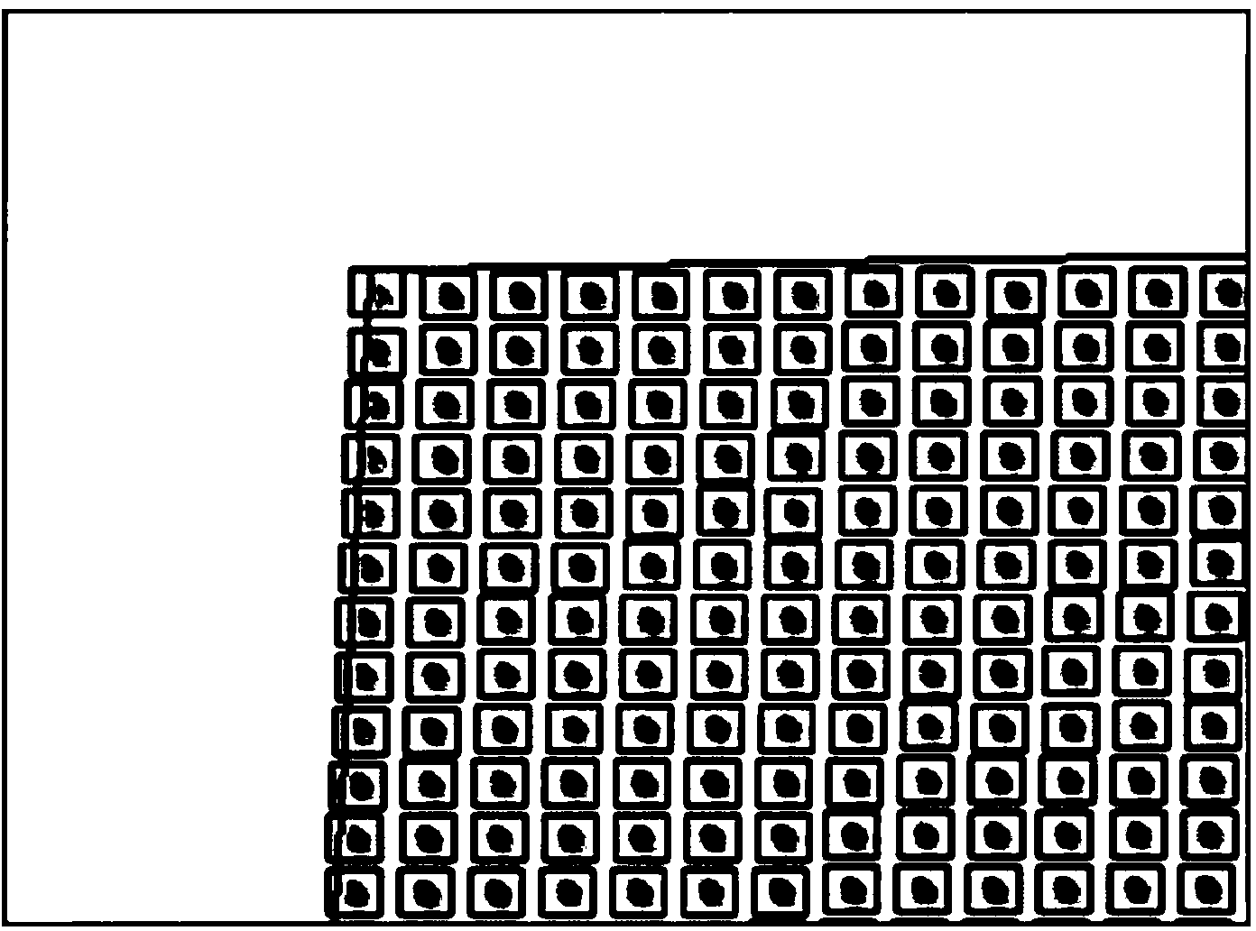
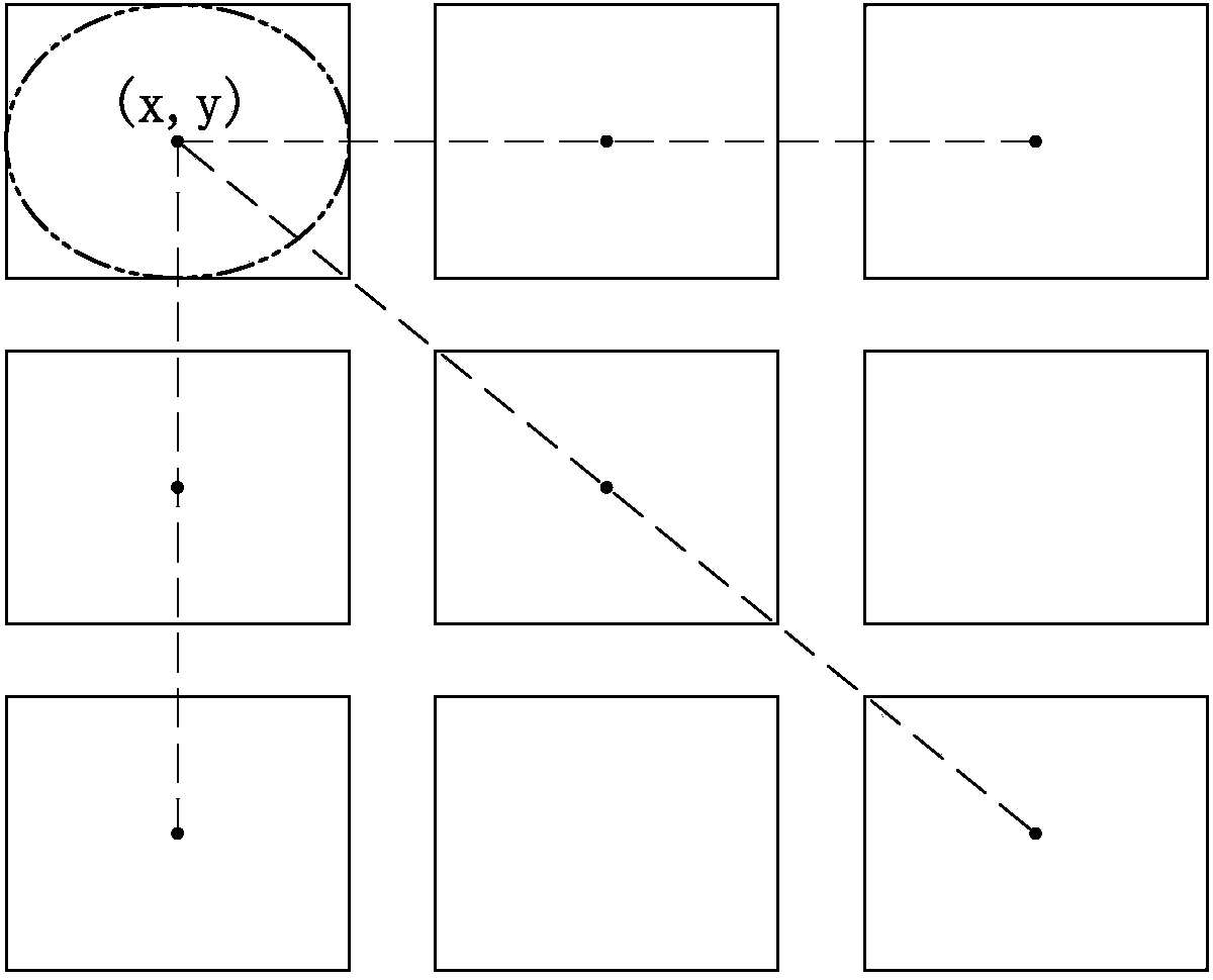
[0033] (1) Obtain any single-color LED cabinet image of red, green, and blue, and locate each LED light point of the LED cabinet to be corrected in the LED cabinet image through image processing and analysis technology. Specifically, it can be: control the LED box to be corrected to display any monochrome picture of red, green, and blue and control the camera to capture the displayed monochrome picture, then the LED box image can be obtained, which is also called the detection of the monochrome image; and then through Image processing and analysis technology locates multiple LED light points o...

no. 2 example

[0045] For the calibration of LED display devices such as LED cabinets in factory mode, the deviation of LED brightness and chromaticity measurement caused by human errors is reduced by intelligently detecting the relative spatial position between the shooting equipment such as a camera and the LED cabinet to be corrected. Another specific implementation The way, for example, is as follows:

[0046] (1) Obtain any single-color LED cabinet image of red, green, and blue, and locate each LED light point of the LED cabinet to be corrected in the LED cabinet image through image processing and analysis technology. Specifically, it can be: control the LED box to be corrected to display any monochrome picture of red, green, and blue and control the camera to capture the displayed monochrome picture, then the LED box image can be obtained, which is also called the detection of the monochrome image; and then through Image processing and analysis technology locates multiple LED light poi...

no. 3 example

[0057] See Figure 9The third embodiment of the present invention provides a system for detecting the spatial position of an LED display device for guiding correction, which is suitable for performing the detection of the spatial position of an LED display device for guiding correction in the aforementioned first embodiment and / or the second embodiment method. Specifically, the LED display device spatial position detection system 90 for guiding correction in this embodiment includes: a shooting control module 91 , a light point selection and center coordinate calculation module 93 , a spatial state difference calculation module 95 and an adjustment prompt output module 97 . Wherein, the photographing control module 91 is used to control the photographing equipment to photograph a monochromatic picture displayed by the LED display device (such as an LED box) to be corrected to obtain a detected monochromatic image and locate the subject to be corrected in the detected monochrom...


PUM


Abstract

The invention relates to an LED display device space position detection method and system for guidance and correction. The LED display device space position detection method comprises the steps of (a) shooting the single-colored frame displayed by an LED display device to be corrected, to obtain a detecting single-colored image and positioning a plurality of LED lamp points of the LED display device to be corrected; (b) calculating first central coordinates of at least three non-collinear LED lamp points selected from the plurality of LED lamp points, respectively located in the detecting single-colored image; (c) utilizing the first central coordinates of the selected LED lamp points and second central coordinates of the selected LED lamp points in a reference single-colored image to calculate the angle and distance difference between a space state and a reference space state of the LED display device to be corrected; (d) outputting a prompt for adjusting the relative space position between a shooting device and the LED display device to be corrected. Therefore, the influence caused by man-made errors in the correction process can be reduced.

Description

technical field [0001] The invention relates to the technical field of LED display correction, in particular to a method and system for detecting the spatial position of an LED display device for guiding correction. Background technique [0002] At present, the most efficient and practical calibration method in the LED display device calibration industry is point-by-point calibration based on camera measurement combined with pulse width modulation (PWM). The so-called camera measurement refers to using a camera as a measurement device to collect the relative or absolute brightness of the LED on the display device. To calculate the brightness and chromaticity correction coefficient of the LED; the so-called pulse width modulation refers to adjusting the current with different pulse widths according to the LED correction coefficient value to make the brightness and chromaticity of the LED display device uniform. [0003] Since this point-by-point calibration method requires a ...

Claims


Application Information

Patent Timeline
Patent Type & Authority Applications(China)
IPC IPC(8): G01B11/00G09G3/32
Inventor 杨城赵星梅
Owner XIAN NOVASTAR TECH
Why Eureka
Try Eureka