
Focusing structure, lens module and camera module provided with lens module

A lens module and lens technology, applied to cameras, camera focusing devices, focusing devices, etc., can solve problems affecting the quality of lens modules, polluting modules, and damaging motors, etc.

Inactive Publication Date: 2015-01-14
NANCHANG O FILM OPTICAL ELECTRONICS TECH CO LTD +3
View PDF11 Cites 6 Cited by
  • Summary
  • Abstract
  • Description
  • Claims
  • Application Information

AI Technical Summary

Problems solved by technology

[0002] At present, the traditional autofocus module of the lens module is composed of a voice coil motor and a gear or screw transmission structure, and the movement of the motor is controlled by the drive circuit to control the movement of the lens, so as to realize the focusing function of the lens; the voice coil motor is mainly The smooth and continuous movement of the lens load is realized by the force generated by the magnet when the spring and the coil are energized; however, the torque control between the lens assembly and the motor is extremely important. The motor is easily damaged if the torque is large, and the lens is easy to lose focus if the torque is small. Moreover, the cooperative friction of gears or threads is likely to generate friction dust and pollute the module, affecting the quality of the lens module

Method used


Image

  • Focusing structure, lens module and camera module provided with lens module
  • Focusing structure, lens module and camera module provided with lens module
  • Focusing structure, lens module and camera module provided with lens module

Examples


Embodiment Construction

[0021] The following will clearly and completely describe the technical solutions in the embodiments of the present invention with reference to the accompanying drawings in the embodiments of the present invention. Obviously, the described embodiments are only some, not all, embodiments of the present invention. Based on the embodiments of the present invention, all other embodiments obtained by persons of ordinary skill in the art without making creative efforts belong to the protection scope of the present invention.

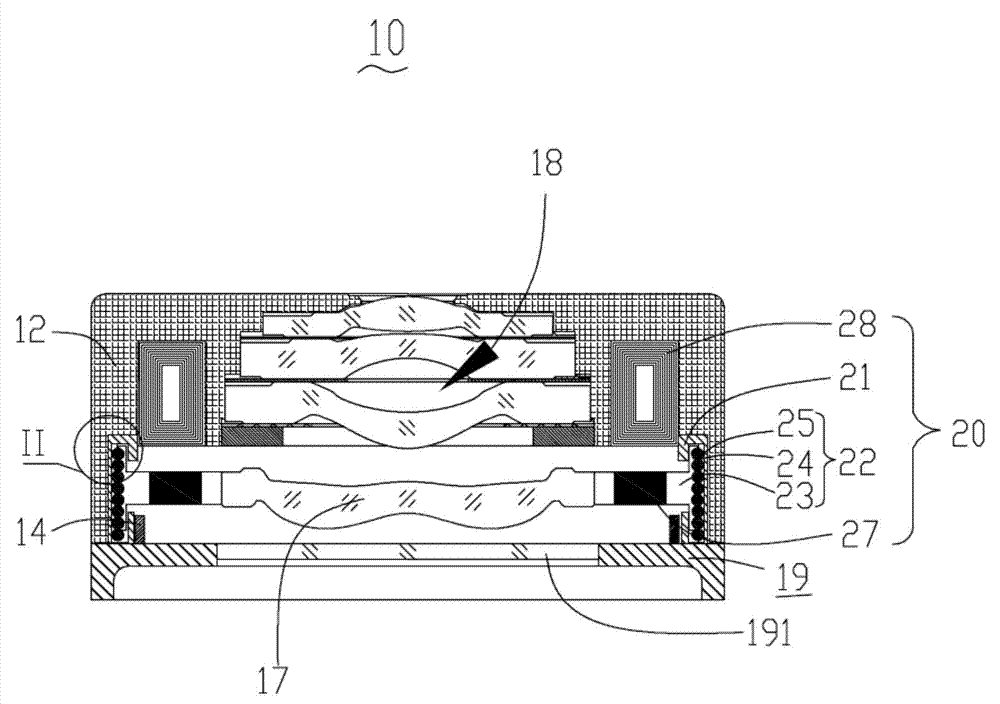
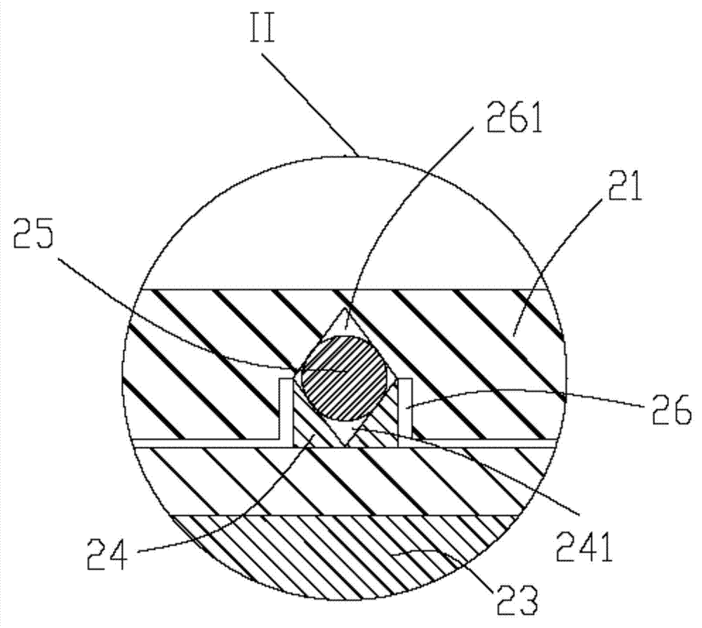
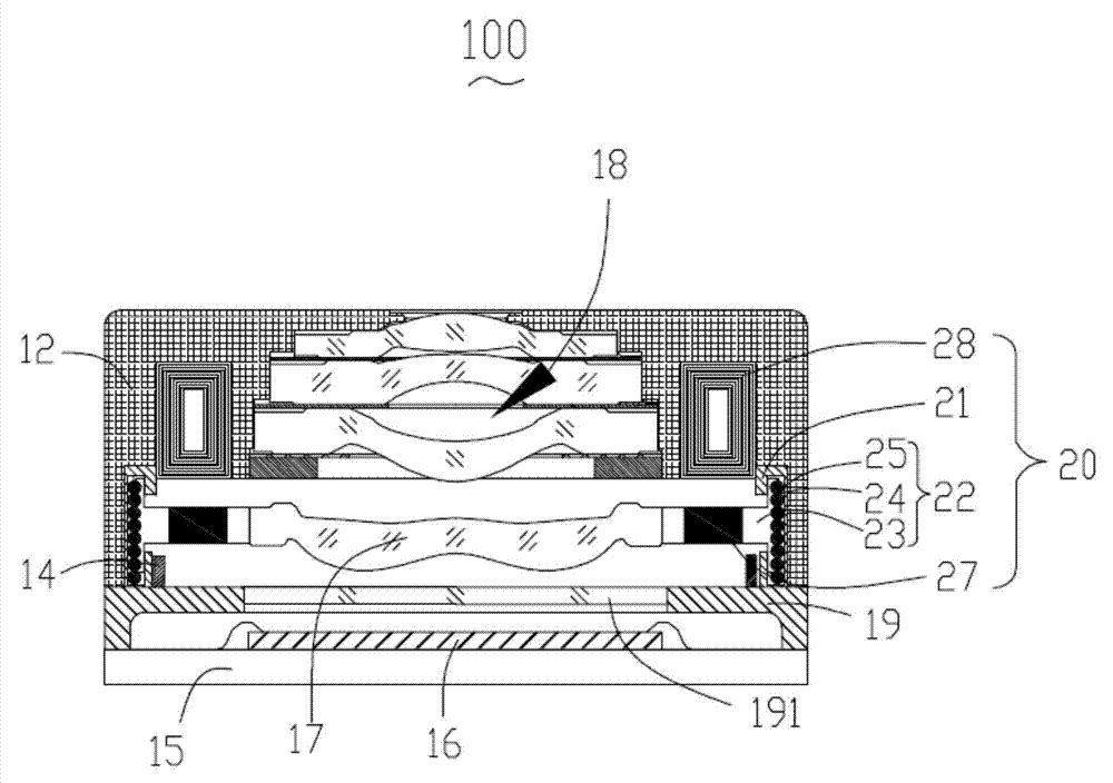
[0022] see figure 1 and figure 2 , the preferred embodiment of the present invention provides a focusing structure 20 for focusing the focusing lens 17 in the lens module. The focusing structure 20 includes a base 21 , a movable part 22 , a magnet 27 and a coil 28 located on the edge of the base 21 . The movable part 22 includes a movable piece 23 and a plurality of balls 25 . The middle part of the movable piece 23 is provided with a mounting hole (not ma...


PUM


Abstract

The invention provides a focusing structure, a lens module and a camera module provided with the lens module. The focusing structure comprises a base, a movable part, magnets and coils located at the edge of the base. The movable part comprises a movable sheet and a plurality of balls. The middle of the movable sheet is provided with a mounting hole. At least two siding rods are arranged on the peripheral edge of the movable sheet in a spaced mode. The sliding rods are perpendicular to the movable sheet. The base is provided with sliding grooves corresponding to the sliding rods. The inner walls of the sliding grooves are provided with rolling grooves in a concaved mode. The balls are sequentially arranged in the rolling grooves and form rolling surfaces protruding out of the rolling grooves. A focusing lens is contained and fixed into the mounting hole. The magnets are arranged on the movable sheet and surround the mounting hole. The movable sheet is contained in the base. The sliding rods are mounted in the sliding grooves in a sliding mode and abut against the rolling surfaces. The movable sheet is located in the base through frictional force between the sliding rods and the balls. The coils are opposite to the magnets. The invention further provides the lens module and the camera module which are provided with the focusing structure.

Description

technical field [0001] The invention relates to a focusing structure, a lens module and a camera module with the focusing structure. Background technique [0002] At present, the traditional autofocus module of the lens module is composed of a voice coil motor and a gear or screw transmission structure, and the movement of the motor is controlled by the drive circuit to control the movement of the lens, so as to realize the focusing function of the lens; the voice coil motor is mainly The load of the lens can move smoothly and continuously under the force generated by the magnet by energizing the spring and the coil; however, the torque control between the lens assembly and the motor is extremely important, the motor is easy to be damaged if the torque is large, and the lens is easy to lose focus if the torque is small. Moreover, the cooperative friction of gears or threads is likely to generate friction dust and pollute the module, affecting the quality of the lens module. ...

Claims


Application Information

Patent Timeline
IPC IPC(8): G02B7/04G03B13/34
CPCG02B7/04G03B13/34
Inventor 王昕申成哲于立新刘燕妮齐书
Owner NANCHANG O FILM OPTICAL ELECTRONICS TECH CO LTD
Learn More