Vertical-cavity surface-emitting laser radar light source of non-periodic high-contrast grating integrated with rapid angle scanning

A vertical cavity surface emission, non-periodic technology, applied in the direction of lasers, laser components, semiconductor lasers, etc., can solve the problems of not being able to be used as a laser radar light source, small beam deflection angle, and single realization angle, etc., to achieve beam deflection angle Effects of control and focus, large deflection angle, and reduced complexity

Inactive Publication Date: 2018-01-12
CHANGCHUN INST OF OPTICS FINE MECHANICS & PHYSICS CHINESE ACAD OF SCI
View PDF5 Cites 12 Cited by
  • Summary
  • Abstract
  • Description
  • Claims
  • Application Information

AI Technical Summary

Problems solved by technology

[0004] The invention aims to solve the problems of the integrated VCSEL beam control technology that the beam deflection angle is small, the angle is single, scanning cannot be performed, and it cannot be used as a laser radar light source. It provides a vertical cavity surface of an integrated non-periodic high-contrast grating with fast angle scanning. Launch the laser radar light source, which can meet the requirements of the laser radar for the light source

Method used


Image

  • Vertical-cavity surface-emitting laser radar light source of non-periodic high-contrast grating integrated with rapid angle scanning
  • Vertical-cavity surface-emitting laser radar light source of non-periodic high-contrast grating integrated with rapid angle scanning

Examples


Embodiment Construction

[0025] In order to enable those skilled in the art to better understand the technical solutions of the present invention, the present invention will be further described in detail below with reference to the accompanying drawings and embodiments. It should be understood that the specific embodiments described herein are only used to explain the present invention, but not to limit the present invention.

[0026] See figure 1 with figure 2 Shown

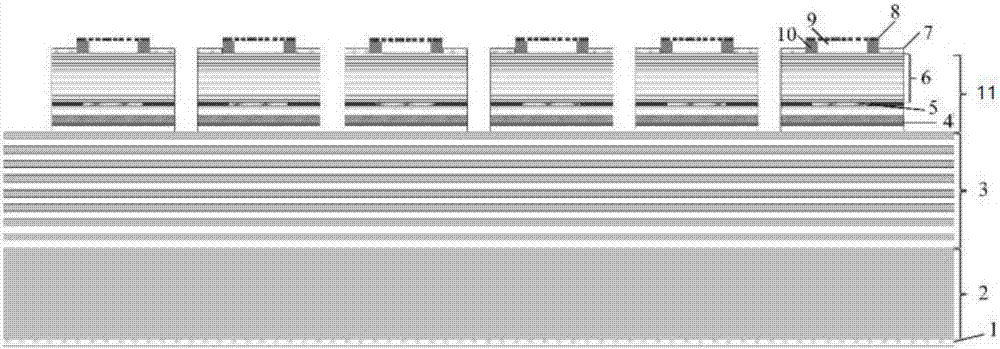
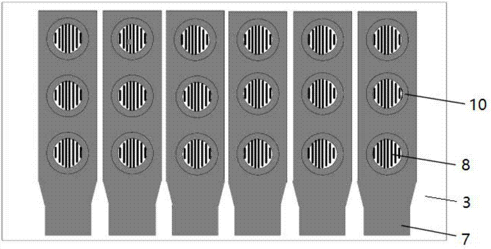
[0027] The angular fast scanning integrated non-periodic high-contrast grating vertical cavity surface emitting laser radar light source of the present invention includes: N-surface electrode 1, substrate 2, N-surface distributed Bragg reflector layer 3, multiple quantum wells, from bottom to top Active gain layer 4, oxidation current confinement hole layer 5, and P-plane distributed Bragg mirror layer 6, the multiple quantum well active gain layer 4, oxidation current confinement hole layer 5, and P-plane distributed Bragg mirror layer 6...


PUM


Abstract

The invention discloses a vertical-cavity surface-emitting laser radar light source of a non-periodic high-contrast grating integrated with rapid angle scanning, and belongs to the technical field ofsemiconductor photoelectrons. The problems that according to a VCSEL, the light beam deflection angle is small, the implementation angle is monotonous and scanning cannot be conducted are solved. Thevertical-cavity surface-emitting laser radar light source comprises a multiple quantum well active gain layer, an oxidized electric current restrictive pore layer and a P-surface distributed Bragg reflector layer from bottom to top in sequence, the multiple quantum well active gain layer, the oxidized electric current restrictive pore layer and the P-surface distributed Bragg reflector layer formfirst mesas, second mesas with air layers in the middle and the diameters smaller than those of the first mesas are arranged on the first mesas, non-periodic high-contrast grating layers are arrangedon the second mesas, and P-surface electrodes are arranged on the outer sides of the first mesas and the second mesas. By means of the vertical-cavity surface-emitting laser radar light source, wide-angle wide view field detection and scanning can be achieved, the complexity of the laser radar light source system is reduced, and requirements for the laser radar light source are met.

Description

Technical field [0001] The invention belongs to the technical field of semiconductor optoelectronics, and in particular relates to a vertical cavity surface emitting laser radar light source for angular fast scanning integrated non-periodic high contrast grating. Background technique [0002] Compared with ordinary microwave radar, LiDAR has great advantages such as high resolution, good concealment, strong anti-interference ability, good low-altitude detection performance, small size and light weight. Lidar is the core component of autonomous navigation of small UAVs, assisted driving or fully automatic driving systems, natural targets, collision avoidance navigation and other fields. LiDAR products currently on the market are bulky, heavy, and expensive, and they use the current mainstream mechanical rotation and ring laser distribution to achieve 360° surround view, which results in a complex LiDAR light source system and expensive unit prices. Therefore, a semiconductor lase...

Claims


Application Information

Patent Timeline
Patent Type & Authority Applications(China)
IPC IPC(8): H01S5/183G01S7/481
Inventor 张星黄佑文宁永强王立军
Owner CHANGCHUN INST OF OPTICS FINE MECHANICS & PHYSICS CHINESE ACAD OF SCI
Why Eureka
Try Eureka