Ion optical device and mass spectrometer

An ion optical device and mass spectrometer technology, applied in the field of mass spectrometry, can solve problems such as complex potential distribution, difficult electrode array, difficult processing, etc., and achieve high flexibility, reduce neutral noise, and low cost

Active Publication Date: 2016-04-06
SHIMADZU SEISAKUSHO LTD
View PDF9 Cites 12 Cited by
  • Summary
  • Abstract
  • Description
  • Claims
  • Application Information

AI Technical Summary

Problems solved by technology

[0006] In view of the shortcomings of the prior art described above, the purpose of the present invention is to provide an ion optical device used in a mass spectrometer to solve the problem that the electrode array in the prior art is difficult to achieve a more complex potential distribution, or even if it can be realized, the structure Technical problems such as complex processing difficulties

Method used


Image

  • Ion optical device and mass spectrometer
  • Ion optical device and mass spectrometer
  • Ion optical device and mass spectrometer

Examples


Embodiment Construction

[0047] Embodiments of the present invention are described below through specific examples, and those skilled in the art can easily understand other advantages and effects of the present invention from the content disclosed in this specification. The present invention can also be implemented or applied through other different specific implementation modes, and various modifications or changes can be made to the details in this specification based on different viewpoints and applications without departing from the spirit of the present invention. It should be noted that, in the case of no conflict, the embodiments in the present application and the features in the embodiments can be combined with each other.

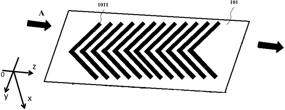
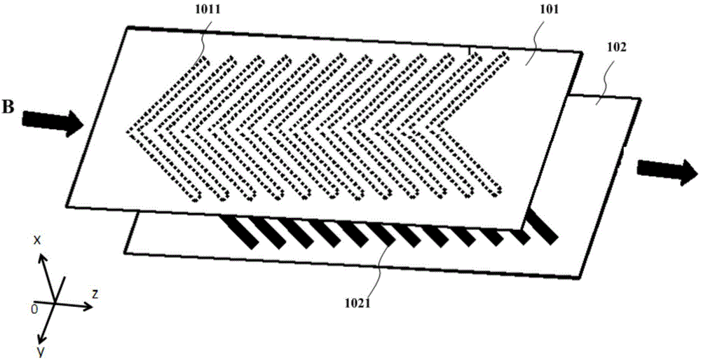
[0048] One of the improvements of the ion optical device of the present invention is to form an electrode array by covering at least one planar insulating substrate with a gold pattern, and use the geometric pattern distribution of the electrode array to form the required e...


PUM


Abstract

The invention provides an ion optical device and a mass spectrometer. The ion optical device comprises at least one planar insulating substrate which is covered with metal patterns to form an electrode array comprising a plurality of cell electrodes, wherein the cell electrodes are arrayed along a first direction to form a geometric pattern distribution of the electrode array; the adjacent and mutually-insulated cell electrodes are applied with radio frequency voltages having different phases to confine ions; a direct current voltage difference is applied between at least part of the cell electrodes in the electrode array to drive ions, which enter an electric field generated by the electrode array, to move in the first direction along the electrode array; and a corresponding electric field distribution is formed by means of the geometric pattern distribution to drive the incident ions to move in a second direction substantially orthogonal to the first direction, thereby realizing ion deflection, focusing or defocusing. Various desired spatial electric field distributions are formed by means of the geometric structure and distribution of the planar electrodes; and in implementation, cell electrodes in various planar geometrical shapes are printed by adopting a PCB or MEMS process, and the ion optical device has the advantages of low cost, high precision, high flexibility and the like.

Description

technical field [0001] The invention relates to the technical field of mass spectrometry, in particular to an ion optical device and a mass spectrometer for a mass spectrometer. Background technique [0002] Ion optics are primarily used in mass spectrometers as ion transport or guide devices to guide ions generated from an ion source into a mass analyzer. Ion optical devices in the form of electrode arrays, such as US patents US6107628, US8581181, and Chinese patent CN201210203634, have been widely used in the industry due to their design and functional flexibility. [0003] At present, the manufacturing method of the electrode array is mainly to directly manufacture discrete pure gold flexor electrode devices, and then use fixtures to position and fix them. The advantages of making pure gold flexor electrodes are that the processing precision can be very high, which is easy to meet the needs of ion optical devices, and the second is that the device itself has no insulatin...

Claims


Application Information

Patent Timeline
Patent Type & Authority Applications(China)
IPC IPC(8): H01J49/06H01J49/26
CPCH01J49/062G01N27/623H01J49/42
Inventor 张小强金峤孙文剑
Owner SHIMADZU SEISAKUSHO LTD
Why Eureka
Try Eureka