Eureka AIR delivers breakthrough ideas for toughest innovation challenges, trusted by R&D personnel around the world.

Compact type energy-saving electromagnetic operating mechanism

An electromagnetic operation and compact technology, applied in the direction of protection switch operation/release mechanism, etc., can solve the problems of excessive height size and uncompact structure, and achieve the effect of reducing height size

Active Publication Date: 2015-01-14
JAECELE ELECTRIC
View PDF5 Cites 2 Cited by
  • Summary
  • Abstract
  • Description
  • Claims
  • Application Information

AI Technical Summary

Problems solved by technology

[0012] Therefore, the technical problem to be solved by the present invention is that the height of the electromagnetic opening and closing mechanism in the "An Electromagnetic Operating Mechanism" submitted by the applicant is too large, and the structure is not compact, resulting in the multi-functional terminal using the electromagnetic opening and closing mechanism The problem that electrical appliances cannot be installed in the commonly used electric meter box due to their high height is too large, so as to provide a compact energy-saving electromagnetic with small height and compact structure, so that the multi-functional terminal electrical appliances can be installed in the commonly used electric meter box operating mechanism

Method used


Image

  • Compact type energy-saving electromagnetic operating mechanism
  • Compact type energy-saving electromagnetic operating mechanism
  • Compact type energy-saving electromagnetic operating mechanism

Examples


Embodiment Construction

[0095] Specific embodiments of the present invention will be described in detail below in conjunction with the accompanying drawings. It should be understood that the specific embodiments described here are only used to illustrate and explain the present invention, and are not intended to limit the present invention.

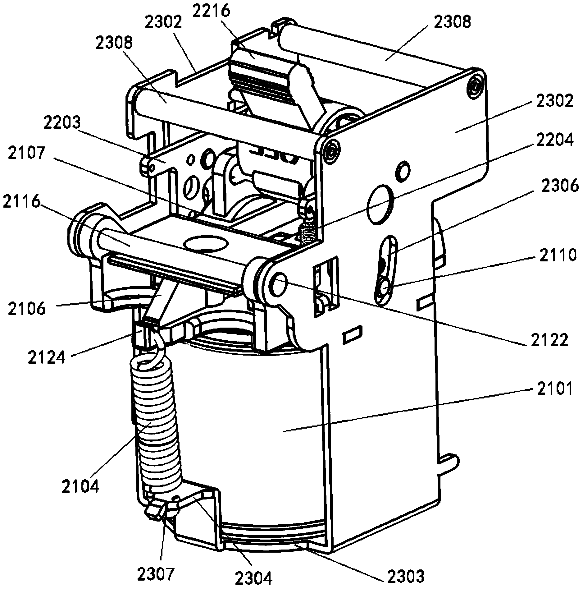
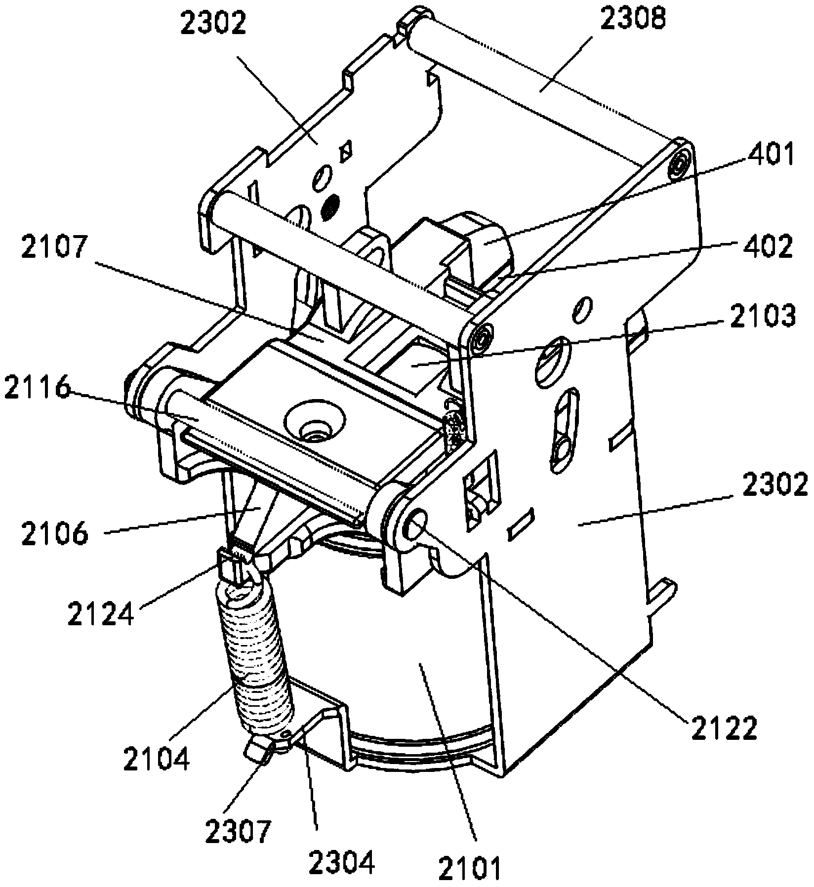
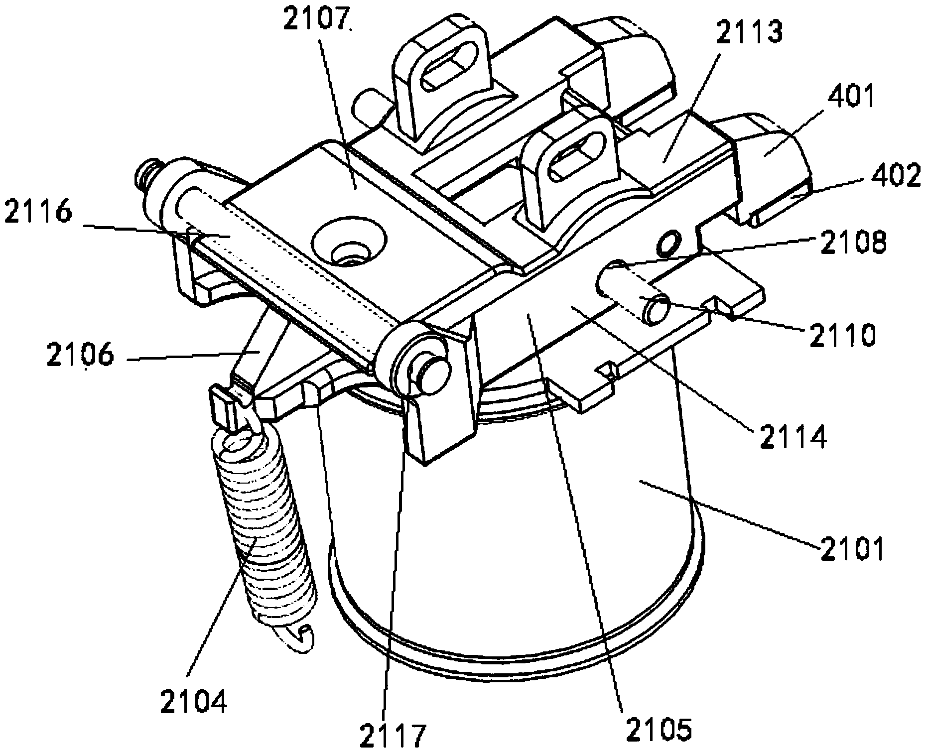
[0096] like figure 1 As shown, this embodiment provides a compact energy-saving electromagnetic operating mechanism, which is suitable for multi-functional terminal appliances equipped with smart meters. The compact energy-saving electromagnetic operating mechanism includes an electromagnetic opening and closing mechanism and an electromagnetic The energy-saving mechanism used by the closing mechanism.

[0097] Wherein, the electromagnetic opening and closing mechanism includes an electromagnetic mechanism and an opening and closing mechanism. The electromagnetic mechanism is similar to the structure of the electromagnetic mechanism in the prior art, including ...


PUM


Abstract

The invention discloses a compact type energy-saving electromagnetic operating mechanism which comprises an electromagnetic mechanism, a counter-force spring and a switch-on and switch-off assembly. The switch-on and switch-off assembly comprises a lever support and a fixed pivot, wherein the lever support is arranged above the electromagnetic mechanism and extends in the horizontal direction, and the fixed pivot enables the lever support to rotate around the lever support. The counter-force spring is connected to one side of the lever support in a hung mode. A movable iron core is connected with the middle appropriate position of the lever support through a matching and connecting structure, and therefore the lever support drives the movable iron core to carry out rectilinear motion without interference through rotation motion. The overall height of the electromagnetic operating mechanism is reduced greatly through the ingenious design of the lever support, and therefore a multifunctional terminal electric appliance using the electromagnetic operating mechanism can be mounted in an electric meter box easily. The compact type energy-saving electromagnetic operating mechanism further comprises an energy-saving mechanism which comprises a lock catch unit and an energy-saving unit. The lock catch unit is used for locking the movable iron core moving to a pull-in position. Meanwhile, the energy-saving unit controls a coil to be powered off, the purpose that the coil of the electromagnetic operating mechanism does not need to be powered on when the electromagnetic operating mechanism is switched on, and a large amount of electric energy is saved.

Description

technical field [0001] The invention relates to an operating mechanism used in circuit breakers, in particular to a compact energy-saving electromagnetic operating mechanism used in multifunctional terminal electrical appliances, and belongs to the technical field of low-voltage electrical accessories. Background technique [0002] The multi-functional terminal appliance refers to the actuator used in conjunction with the smart meter, which is used to accept the instructions sent by the smart meter to open and close the switch, so as to control the user's power on or off. [0003] At present, the commonly used smart meter actuator is a small circuit breaker. When the user owes money, the smart meter sends an opening command to the small circuit breaker, and the small circuit breaker executes the opening, thereby cutting off the power to the arrears users. Through the use of smart meters and actuators, the prepayment mode of electricity is realized, thereby solving the proble...

Claims


Application Information

Patent Timeline
Patent Type & Authority Applications(China)
IPC IPC(8): H01H71/10H01H71/24
CPCH01H71/10H01H71/24
Inventor 彭全昌刘永华
Owner JAECELE ELECTRIC
Why Eureka
Eureka Blog
Learn More