
Self-driven Synchronous Rectification Circuit with Dead Time Topology

A dead time and topology technology, applied in electrical components, output power conversion devices, AC power input conversion to DC power output, etc., can solve the problems of low efficiency of secondary synchronous rectification of high-frequency switching power supply effect of temperature, improving service life and reducing conduction loss

Active Publication Date: 2017-11-10
SHENZHEN RUIJING IND
View PDF2 Cites 0 Cited by
  • Summary
  • Abstract
  • Description
  • Claims
  • Application Information

AI Technical Summary

Problems solved by technology

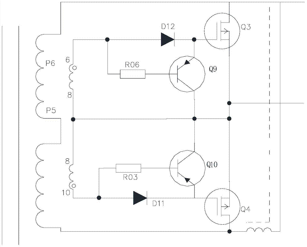
[0006] The purpose of the present invention is to provide a self-driven synchronous rectification circuit with dead time topological structure, which is used to solve the problem of low efficiency of secondary side synchronous rectification of high frequency switching power supply with dead time in the prior art

Method used


Image

  • Self-driven Synchronous Rectification Circuit with Dead Time Topology
  • Self-driven Synchronous Rectification Circuit with Dead Time Topology
  • Self-driven Synchronous Rectification Circuit with Dead Time Topology

Examples


Embodiment Construction

[0018] The present invention will be further elaborated below with reference to the accompanying drawings.

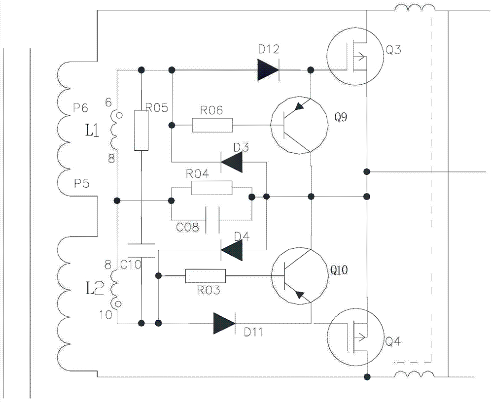
[0019] see figure 2 , the present invention has a self-driven synchronous rectification circuit with a dead time topology, which includes a self-driven winding L1 and L2 connected across the secondary side of the transformer; a rectifier circuit, and the synchronous rectification circuit is connected across the secondary side of the transformer The two ends of the side, more specifically, the synchronous rectification circuit is connected to the two ends of the taps of the self-driving windings L1 and L2; a high-frequency path circuit for continuing to conduct when the circuit is in the dead time, The high-frequency path circuit is coupled to the rectifier circuit, and the high-frequency path circuit includes: a resistor R04, a capacitor C08 connected in parallel to both ends of the resistor R04, and a capacitor C08 connected in parallel with the resistor R04 An RC ne...


PUM


Abstract

A self-driven synchronous rectification circuit with a dead-time topological structure, which includes a rectification circuit coupled to the secondary side of the transformer, the rectification circuit includes a series self-driving winding L1 and L2 for accelerating the turn-off of the driving gate; the coupling A high-frequency path circuit connected between the taps of the self-driving windings L1 and L2 and the accelerated turn-off gate drive circuit; a unidirectional acceleration circuit controlling the signal of the high-frequency path circuit; a peak voltage absorption circuit, wherein , the turn-on time of the high-frequency path circuit is not greater than the dead time of the circuit. The present invention improves the working efficiency of the switching power supply by adding a high-frequency pass circuit and a unidirectional acceleration pass diode in the self-driven rectification circuit, and reduces the deep conduction time of the body diode of the MOS tube during the dead time, Therefore, the temperature of the MOS tube is reduced, the service life of the MOS tube is improved, and the power supply is more stable.

Description

technical field [0001] The invention relates to the technical field of secondary side rectification circuits of high-frequency switching power supplies, in particular to a self-driven synchronous rectification circuit with a dead-time topological structure. Background technique [0002] With the promotion of the concept of energy saving and environmental protection around the world, energy saving and emission reduction have gradually become popular among the people. On the one hand, it is necessary to vigorously develop green and environmentally friendly new energy sources, and on the other hand, it is to reduce the loss of existing energy sources and improve energy utilization efficiency. For example, in the field of high-frequency switching power supply design, the secondary side synchronous rectification technology of the power supply has been widely used, such as flyback circuit, synchronous rectification of forward circuit, etc. However, for circuits with dead time top...

Claims


Application Information

Patent Timeline
Patent Type & Authority Patents(China)
IPC IPC(8): H02M7/162H02M1/32
CPCH02M1/32H02M7/217H02M1/327
Inventor 王彤王爱军
Owner SHENZHEN RUIJING IND
Learn More