
Multistage passive optical network fault monitoring system and implementation method thereof

A passive optical network and fault monitoring technology, applied in transmission systems, electromagnetic wave transmission systems, electrical components, etc., can solve the problems of lack of effective measurement methods and insufficient cross-platform performance in multi-level passive optical networks

Active Publication Date: 2015-01-14
SHANGHAI JIAO TONG UNIV
View PDF7 Cites 11 Cited by
  • Summary
  • Abstract
  • Description
  • Claims
  • Application Information

AI Technical Summary

Problems solved by technology

[0014] Aiming at the defects in the prior art, the technical problem solved by the present invention is: to overcome the deficiency of the cross-platform performance of the existing OTDR host computer test software, to propose a cross-platform solution, to reduce the development cycle and transplant complexity, and reduce the Cost; overcome the lack of effective measurement means for multi-level passive optical networks in the prior art, and provide a system and implementation method for fault monitoring of passive optical networks. Passive optical network for detection; overcome the deficiencies of existing technologies, provide automatic save / restore function of reference data, simplify the operation process of testers and save time

Method used


Image

  • Multistage passive optical network fault monitoring system and implementation method thereof
  • Multistage passive optical network fault monitoring system and implementation method thereof
  • Multistage passive optical network fault monitoring system and implementation method thereof

Examples


Embodiment Construction

[0104] The present invention will be described in detail below in conjunction with specific embodiments. The following examples will help those skilled in the art to further understand the present invention, but do not limit the present invention in any form. It should be noted that those skilled in the art can make several modifications and improvements without departing from the concept of the present invention. These all belong to the protection scope of the present invention.

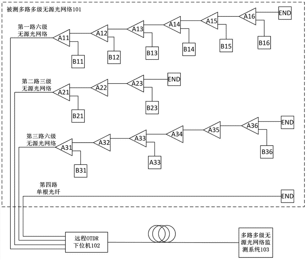
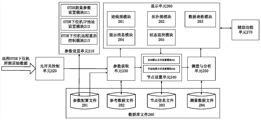
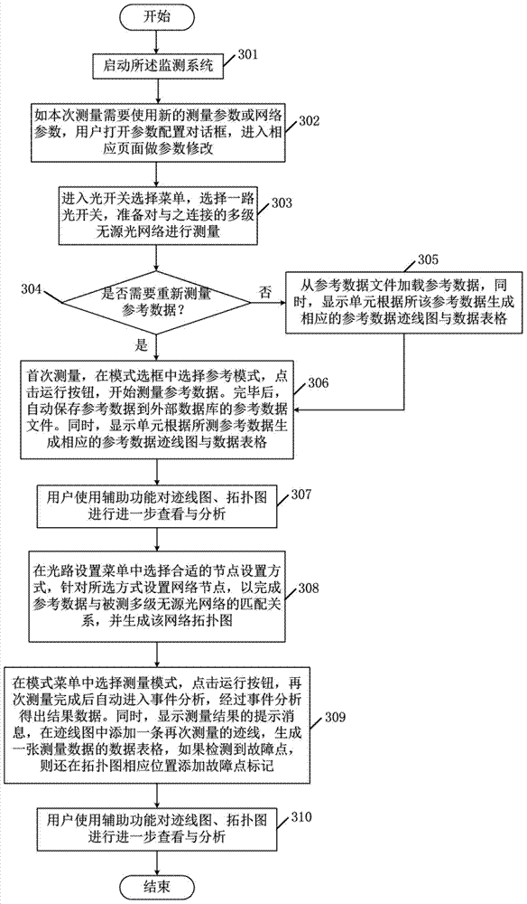
[0105] Embodiments of the present invention will describe a multi-stage passive optical network fault monitoring system and its implementation method provided in conjunction with the accompanying drawings, including: a schematic diagram of the overall OTDR system and several typical measured optical paths; the composition of the monitoring software of the present invention Each unit module of the system and their respective functions and functions; the realization method of key technologies; the st...


PUM


Abstract

The invention discloses a multistage passive optical network fault monitoring system and an implementation method. The multistage passive optical network fault monitoring system comprises a parameter setting unit, an optical switch control unit, a parameter acquisition unit, a node setting unit, a measurement and analysis unit and a display unit, wherein the parameter setting unit is used for setting measurement parameters; the optical switch control unit is used for switching channels used for measurement; the parameter acquisition unit is used for acquiring reference data according to the measurement parameters and an optical switch; the node setting unit is used for setting network nodes for the reference data; the measurement and analysis unit is used for conducting measurement again and carrying out event analysis according to the reference data, the network nodes and data measured again to obtain result data; the display unit is used for displaying the result data and the running state which is monitored currently in a diversified mode. By means of the multistage passive optical network fault monitoring system and the implementation method, fault monitoring of a multi-path multistage passive optical network through an OTDR is achieved, and universality, cross-platform and the like of current optical fiber measurement software are realized.

Description

technical field [0001] The invention belongs to the field of test and measurement and the field of computers, and relates to a system for monitoring faults of a multi-channel multi-stage passive optical network (Passive Optical Network PON) by using an optical time domain reflectometry (OTDR) and an implementation method thereof Specifically, it relates to a method for monitoring multilevel passive optical networks by measuring reference data and retest data, and a system for monitoring faults in passive optical networks realized by using the wxWidgets cross-platform programming framework. Background technique [0002] With the rapid development of my country's communication industry, optical fiber, as a communication carrier, plays an important role in high-speed, large-capacity, and long-distance communications due to its advantages such as low loss, wide transmission frequency bandwidth, large capacity, small size, light weight, and anti-electromagnetic interference. play ...

Claims


Application Information

Patent Timeline
IPC IPC(8): H04B10/077
Inventor 马成孔衡周潜谢玮霖董毅
Owner SHANGHAI JIAO TONG UNIV
Learn More