Channel safety transmission method

A technology of secure transmission and channel, applied in the field of communication

Active Publication Date: 2015-01-14
UNIV OF ELECTRONICS SCI & TECH OF CHINA
View PDF3 Cites 13 Cited by
  • Summary
  • Abstract
  • Description
  • Claims
  • Application Information

AI Technical Summary

Problems solved by technology

[0013] In the existing research, the optimal security rate of the system is only obtained in the DF forwarding mode, and the suboptimal security rate of the system can only be determined under the AF or CJ strategy. , it is necessary to further improve its feasible security rate and improve the utilization rate of system resources

Method used


Image

  • Channel safety transmission method
  • Channel safety transmission method
  • Channel safety transmission method

Examples


Embodiment 1

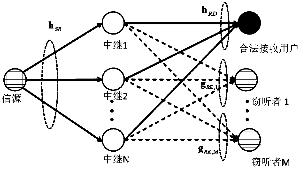
[0107] This example aims at the problem of maximizing the system's achievable security rate when there are two eavesdroppers and the channel state information CSI is not perfectly known.

[0108] random channel h SR and h RD Created by

[0109] h SR = h rand 1 2 + j h rand 1 2

[0110] h RD = h rand 2 2 + j h rand 2 2

[0111] h rand1 and h rand2 are Nre×Nt and Nre×Nr random matrices subject ...


PUM


Abstract

The invention discloses a channel safety transmission method and belongs to the technical field of communication technologies. The channel safety transmission method comprises the steps of determining signal weight factors v and man-made noise nJ of relay nodes when signals are forwarded, based on maximized optimization processing of corresponding safe capacities of the relay nodes in the information forwarding process during preprocessing; respectively multiplying received source information by the signal weight factors v of the relay nodes and then adding the man-made noise nJ to products to serve as signals to be transmitted in the next step when a system works, namely the man-made noise is sent while the relay nodes collaboratively forward signals. The channel safety transmission method is mainly applied to physical-layer safety communication, the maximum reachable safety speed of the system is improved, and the purpose of improving the safety performance of the system is achieved.

Description

technical field [0001] The present invention relates to communication technology, in particular to physical layer security communication technology when there is relay. Background technique [0002] With the development of wireless communication technology, information security technology based on physical layer has become a research hotspot in the field of wireless communication and information security. Effectively utilizing the physical layer resources of wireless communication systems, researching information security technologies based on physical layer resources, and exploring new methods that can effectively improve the security of wireless communication systems have far-reaching theoretical significance and practical application value. [0003] The broadcast feature of wireless communication makes information easy to be stolen by eavesdroppers during transmission. Traditionally, some cryptographic protocols are designed on the upper layer to provide secure communica...

Claims


Application Information

Patent Timeline
Patent Type & Authority Applications(China)
IPC IPC(8): H04K3/00H04W52/24H04W52/26H04W88/04
Inventor 孔卫庆陈智李玲香徐禹
Owner UNIV OF ELECTRONICS SCI & TECH OF CHINA
Why Eureka
Try Eureka