Ultrasonic scanning method and ultrasonic scanning system

A scanning method and scanning system technology, which are used in radio wave measurement systems, ultrasonic/sonic/infrasonic diagnosis, material analysis using sonic/ultrasonic/infrasonic waves, etc., can solve problems affecting the accuracy of ultrasonic composite images, and improve the The effect of accuracy

Inactive Publication Date: 2015-01-21
QISDA SUZHOU +1
View PDF11 Cites 4 Cited by
  • Summary
  • Abstract
  • Description
  • Claims
  • Application Information

AI Technical Summary

Problems solved by technology

However, ultrasonic images generated by ultrasonic signals emitted and received from oblique angles often produce side lobes, artifacts, or other noises, thereby affecting the accuracy of ultrasonic composite images

Method used


Image

  • Ultrasonic scanning method and ultrasonic scanning system
  • Ultrasonic scanning method and ultrasonic scanning system
  • Ultrasonic scanning method and ultrasonic scanning system

Examples


Embodiment Construction

[0047] In order to have a further understanding of the purpose, structure, features, and functions of the present invention, the following detailed descriptions are provided in conjunction with the embodiments.

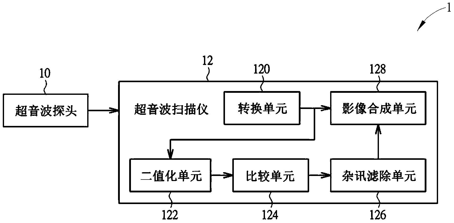
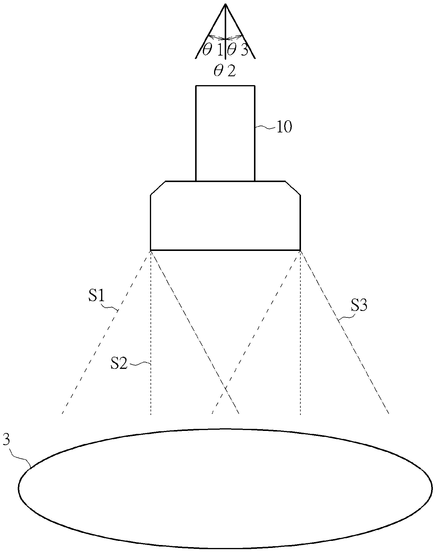
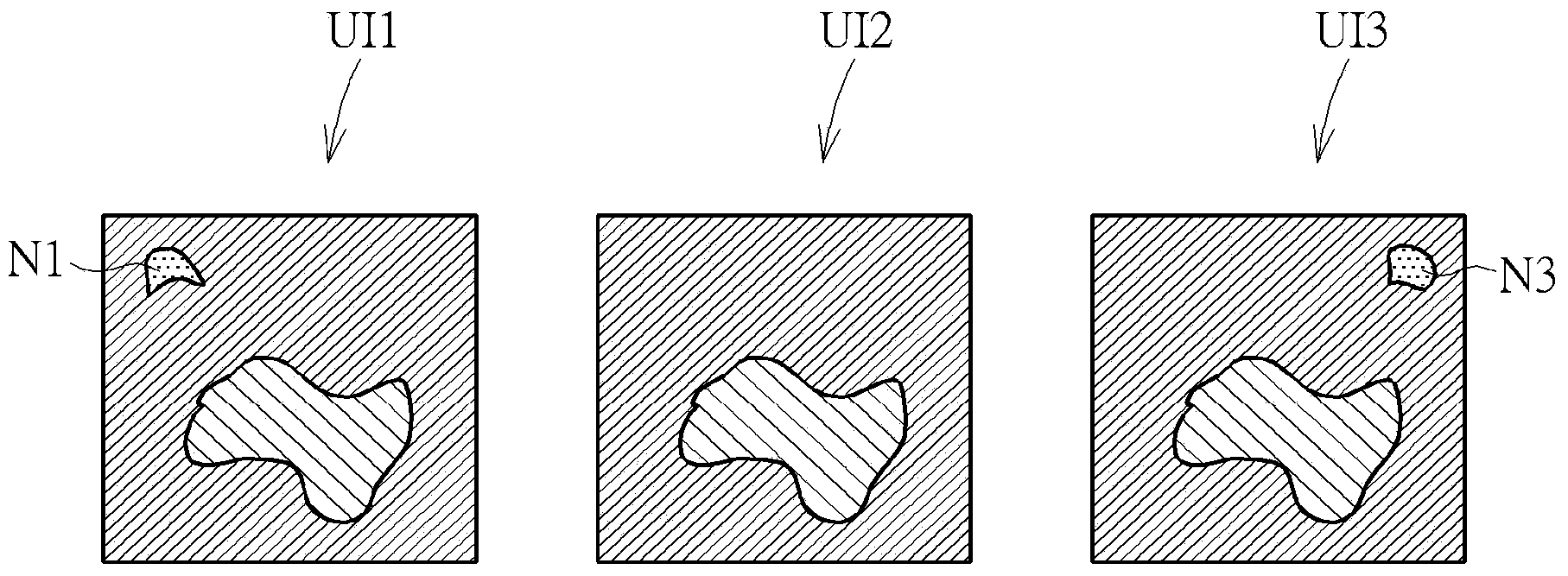
[0048] see Figure 1 to Figure 6 , figure 1 It is a functional block diagram of an ultrasonic scanning system 1 according to an embodiment of the present invention, figure 2 for figure 1The schematic diagram of ultrasonic probe 10 performing ultrasonic scanning on the target object 3, image 3 for figure 1 Ultrasound scanner in 12 according to figure 2 Schematic diagrams of the ultrasonic input images UI1, UI2, and UI3 generated by the scanning results in , Figure 4 for figure 1 The ultrasound scanner in 12 will image 3 Schematic diagram of converting the ultrasonic input images UI1, UI2, and UI3 into binarized images BI1, BI2, and BI3 in Figure 5 for image 3 The ultrasonic input image UI1, UI2, UI3 in the figure is a schematic diagram of the ultrasonic...


PUM


Abstract

The invention provides an ultrasonic scanning method. The method includes the steps of emitting N groups of ultrasonic signals at N different angles towards an object and receiving the N groups of ultrasonic signals reflected and/or scattered from the target; converting the N groups of ultrasonic signals into N ultrasonic input images; subjecting the N ultrasonic input images to a binarization algorithm so as to obtain N binary images; subjecting the N binary images to comparison so as to judge whether or not at least one of the N binary images has noise; if yes, filtering the noise from the i-th binary image corresponding to the i-th binary image; and synthesizing the N ultrasonic input images into an ultrasonic output image. Each group of ultrasonic signals correspond to one of the N different angles, with N being a positive integer greater than 1 and i being a positive integer less than or equal to N.

Description

technical field [0001] The present invention relates to an ultrasonic scanning method and an ultrasonic scanning system, in particular to an ultrasonic scanning method and an ultrasonic scanning system capable of effectively filtering noise. Background technique [0002] Because ultrasonic scanning has the characteristics of not destroying the structure of materials and human cells, it is widely used in the field of materials and clinical medical testing. Because composite images can provide better resolution, composite images have been widely used in ultrasonic scanning systems. The technical principle of the composite image must first transmit and receive ultrasonic signals from multiple different angles, and then synthesize the ultrasonic images corresponding to the multiple different angles into a composite ultrasonic image. However, ultrasonic images generated by ultrasonic signals emitted and received from oblique angles often produce side lobes, artifacts, or other n...

Claims


Application Information

Patent Timeline
Patent Type & Authority Applications(China)
IPC IPC(8): A61B8/00G01N29/00
CPCA61B8/00A61B8/5238G01S7/52017G01S7/52047G01S15/8995
Inventor 陈翔洲郭富彦
Owner QISDA SUZHOU
Why Eureka
Try Eureka