Respiratory assistance devices capable of estimating the flow rate of gas exiting through the exhalation valve

A technology of gas flow rate and exhalation valve, which can be used in respirator, drug equipment, other medical equipment, etc., and can solve the problems of facial discomfort, bulky, deformation, etc.

Inactive Publication Date: 2018-02-06
AIR LIQUIDE MEDICAL
View PDF9 Cites 0 Cited by
  • Summary
  • Abstract
  • Description
  • Claims
  • Application Information

AI Technical Summary

Problems solved by technology

[0008] Today, the disadvantages of such an additional measuring module are inter alia: the weight exerted on the patient's mouth causes discomfort, deformation, etc. of the face, and the addition of considerable additional lines between the device and the module / patient gets in the way and leads to bulk huge

Method used


Image

  • Respiratory assistance devices capable of estimating the flow rate of gas exiting through the exhalation valve
  • Respiratory assistance devices capable of estimating the flow rate of gas exiting through the exhalation valve
  • Respiratory assistance devices capable of estimating the flow rate of gas exiting through the exhalation valve

Examples


Embodiment Construction

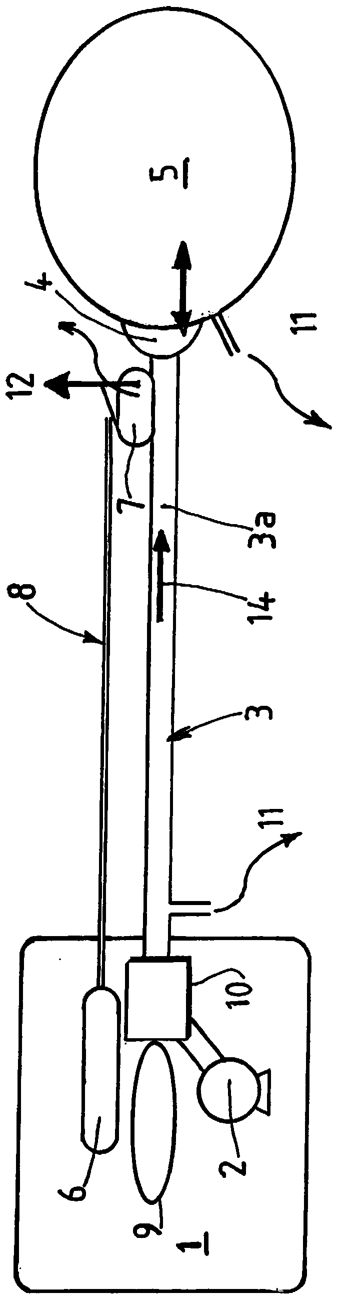
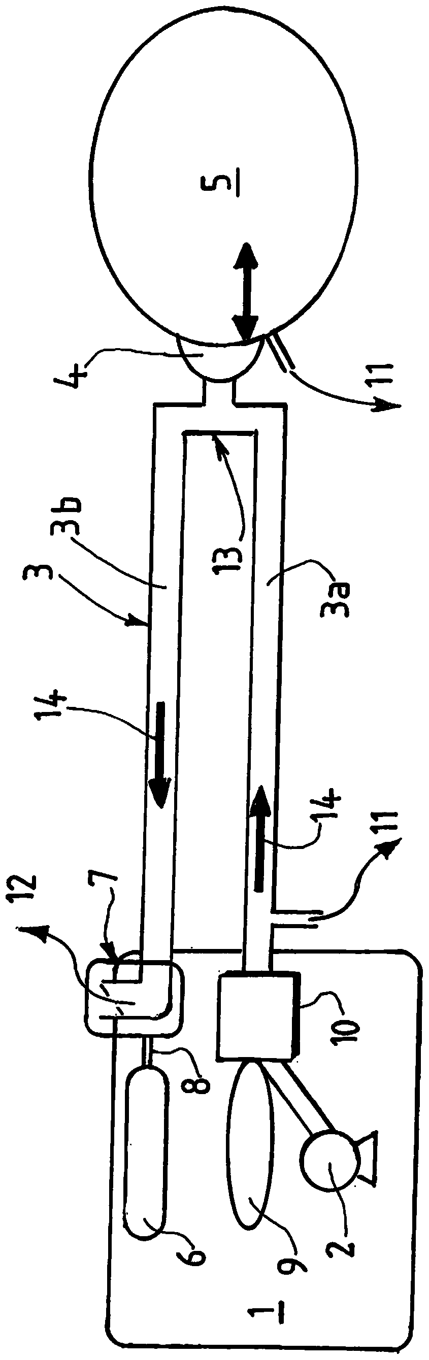
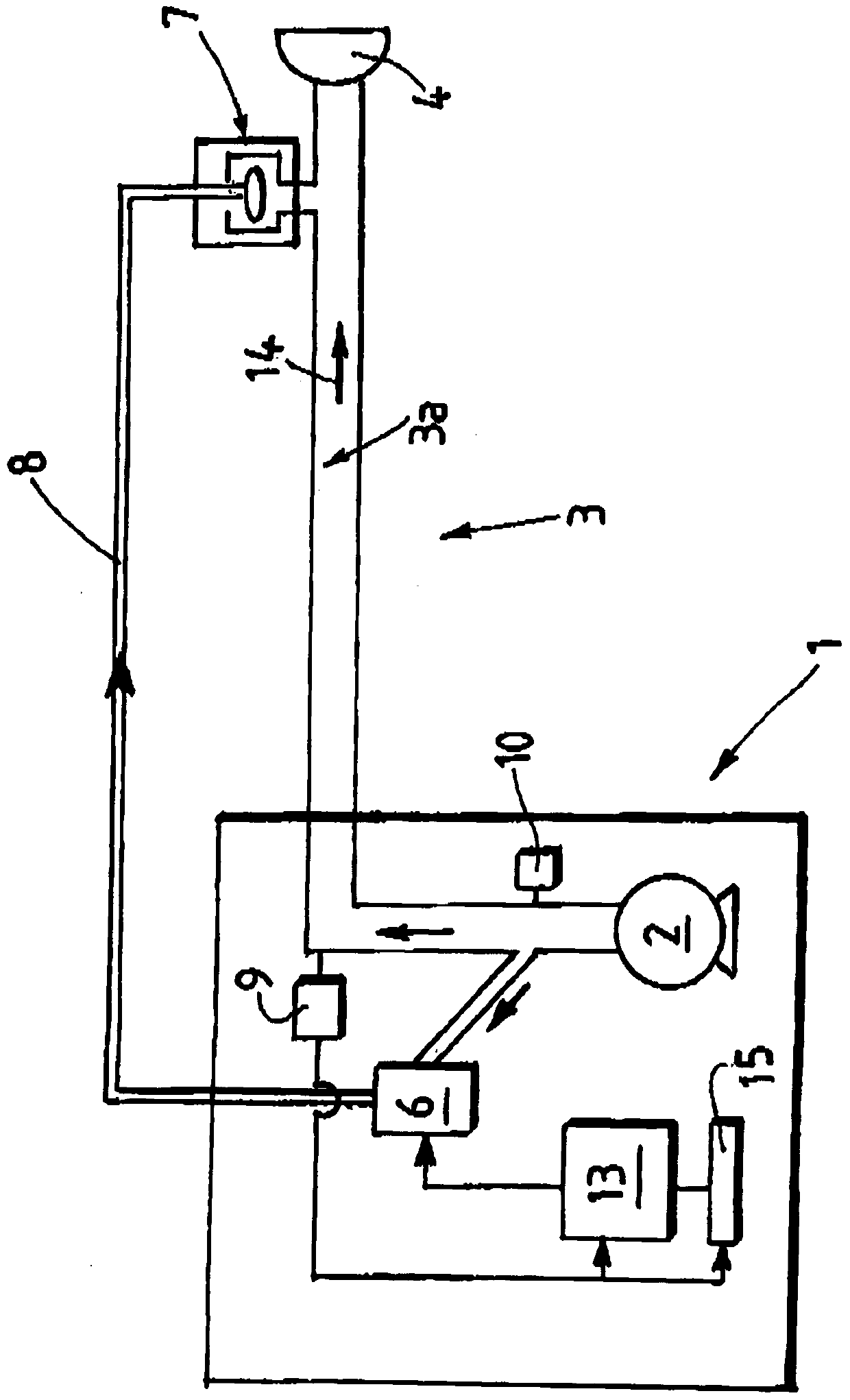
[0073] figure 1 and image 3 Shown is a first embodiment of an artificial respiration device 1 , i.e. a medical ventilator, for example the Monnal T50 ventilator commercially available by the applicant, which according to the invention comprises a patient circuit 3, the patient The circuit 3 has a single breathing limb 3a, also referred to as an inhalation limb, which is fluidly supplied by a gas source 2, such as a turbine or a micro-fan, or a gas source 2 fluidly connected to the in-wall gas network of the ventilator 1, so that the Gas (eg air) is delivered to the patient 5 under pressure, ie at a pressure greater than atmospheric pressure (ie >1 atm).

[0074] The patient circuit 3 enables delivery of gas from a gas source 2 to a patient interface 4 , such as a mask or an endotracheal or intubation probe, which enables delivery of gas to a patient 5 . Arrow 14 schematically shows the direction of gas flow.

[0075] The valve control device comprising the pressurized line...


PUM


Abstract

The invention relates to an artificial respiration device (1) for a patient (5), comprising a gas source (2) and a patient circuit (3, 3a, 3b) with exhalation controlled by a pressurized line (8) Valve (7), the pressurized line includes a solenoid valve (6) controlled by drive means (13). Driving means deliver a voltage signal (U) to said solenoid valve to control said solenoid valve in order to transmit pressure to said exhalation valve (7) via said pressurizing line (8) and thus according to said voltage signal (U ) controls said exhalation valve (7) between at least a fully open position, a fully closed position and one or more intermediate positions. The pressure measuring device (10) measures the pressure (P) of the gas delivered by the gas source (2). The microprocessor means executes an algorithm capable of determining the gas flow rate (Qve) exiting through said exhalation valve (7) based on the pressure signal (P) and the voltage signal (U).

Description

technical field [0001] The invention relates to an artificial respiration device for a patient or a medical ventilator, which allows the estimation of unintentional air leakage between the artificial respiration device and the patient supplied with air by said respiration device. Background technique [0002] Respiratory apparatus or devices comprising an exhalation valve typically have means for measuring the flow rate leaving the exhalation valve or means for measuring the patient flow rate, ie the proximal flow rate. [0003] In practice, in the absence of such a device for measuring the flow rate leaving the exhalation valve, these devices are not able to monitor data that would help the physician monitor the progress of the treatment (such as a leak between the device and the patient), despite knowing that The patient's ventilation, such as his or her breathing rate. [0004] Thus, the monitoring of estimates of leaks is fairly well controlled when the flow rates into ...

Claims


Application Information

Patent Timeline
Patent Type & Authority Patents(China)
IPC IPC(8): A61M16/00
CPCA61M16/205A61M16/024A61M16/206A61M2016/0027A61M2016/0039A61M2205/15A61M2205/50A61M2205/52A61M2205/70
Inventor G·莫兰
Owner AIR LIQUIDE MEDICAL
Why Eureka
Try Eureka