A sand box transfer device

A transfer device and sand box technology, which is applied in the direction of mold handling equipment, metal processing equipment, casting equipment, etc., to achieve the effects of reducing labor usage, reducing labor costs, and facilitating control and adjustment

Active Publication Date: 2016-04-20
湖州鼎盛机械科技股份有限公司
View PDF9 Cites 0 Cited by
  • Summary
  • Abstract
  • Description
  • Claims
  • Application Information

AI Technical Summary

Problems solved by technology

[0006] In order to solve the defects of manual transportation of sand boxes, the present invention provides a special device for transporting sand boxes. The device realizes the transportation of sand boxes without manual participation, greatly improves work efficiency, and reduces the amount of labor used. Reduce the production cost of the enterprise

Method used


Image

  • A sand box transfer device
  • A sand box transfer device
  • A sand box transfer device

Examples


Embodiment 1

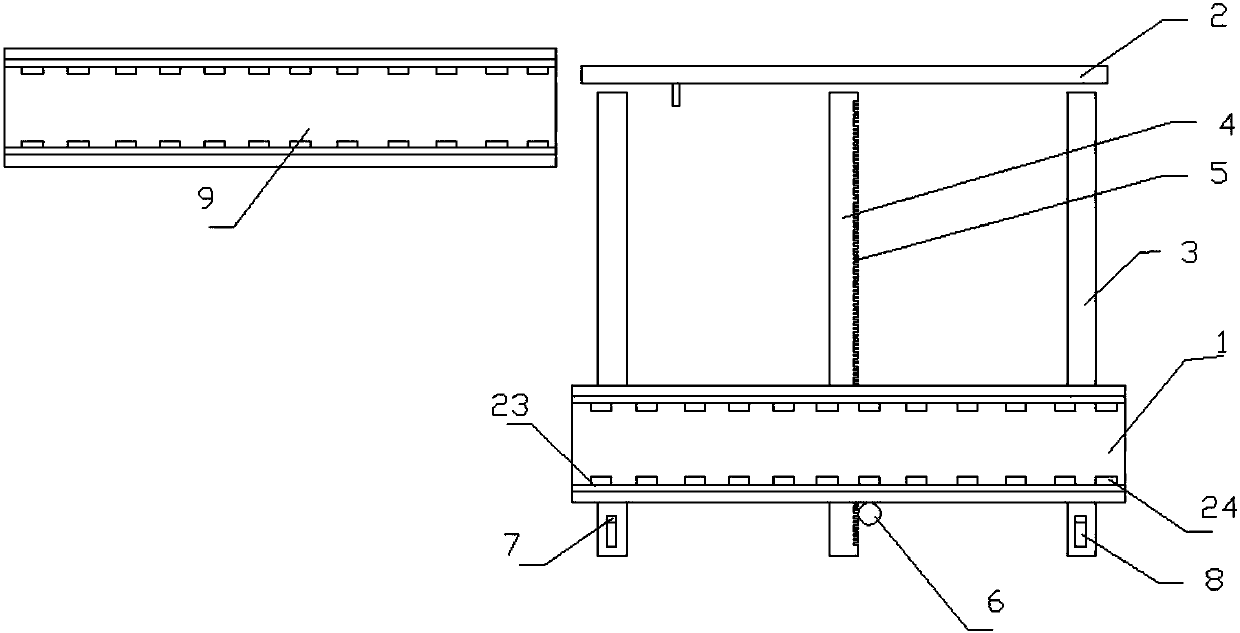
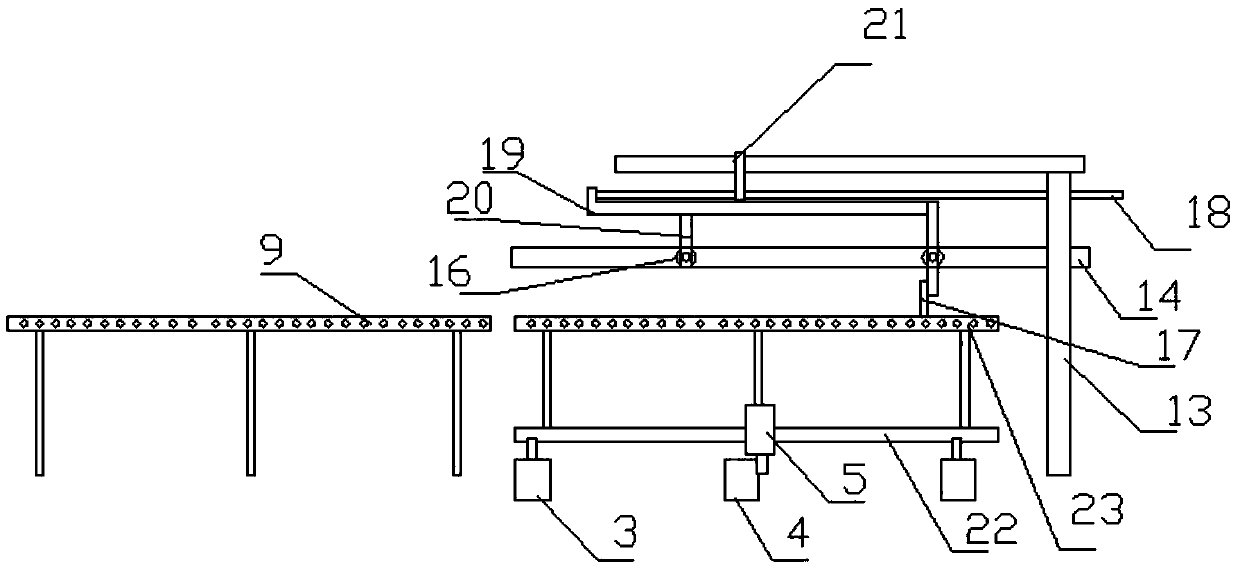
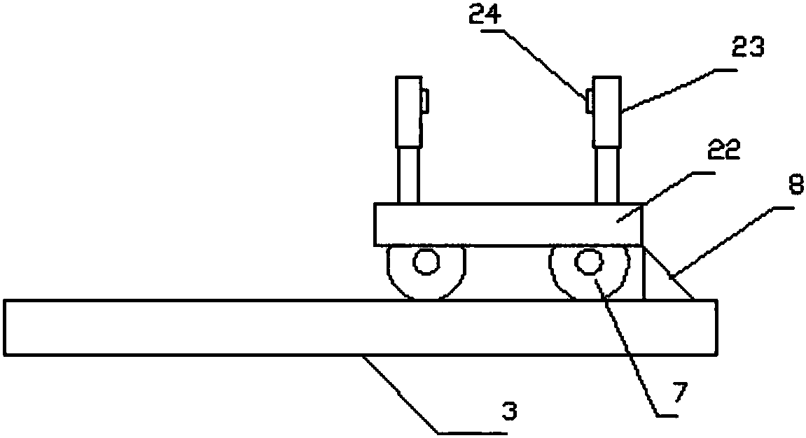
[0039] The present embodiment comprises conveying track 3, conveying trolley 1 and pushing device 2, and described conveying trolley 1 is installed on conveying track 3, and conveying trolley 1 can slide on conveying track 3, and one end of conveying track 3 is provided with described pushing Device 2, the conveying trolley 1 includes a base plate 22, rollers 7 and a transport frame 23, the rollers 7 are arranged on the bottom surface of the base plate 22, and are located in the transport track 3, the transport frame 23 is arranged on the upper surface of the base plate 22, and the transport frame 23 A plurality of transport wheels 24 are provided.

[0040] Drive track 4 is laid between conveying track 3, and drive track 4 is provided with drive rack 5, and described transport trolley 1 is provided with drive gear and drive motor 6, and described drive gear meshes with drive rack 5, and drive gear Socketed on the output shaft of the drive motor 6.

[0041] Limiting blocks are...

Embodiment 2

[0044] The present embodiment comprises conveying track 3, conveying trolley 1 and pushing device 2, and described conveying trolley 1 is installed on conveying track 3, and conveying trolley 1 can slide on conveying track 3, and one end of conveying track 3 is provided with described pushing Device 2, the conveying trolley 1 includes a base plate 22, rollers 7 and a transport frame 23, the rollers 7 are arranged on the bottom surface of the base plate 22, and are located in the transport track 3, the transport frame 23 is arranged on the upper surface of the base plate 22, and the transport frame 23 A plurality of transport wheels 24 are provided.

[0045] Drive track 4 is laid between conveying track 3, and drive track 4 is provided with drive rack 5, and described transport trolley 1 is provided with drive gear and drive motor 6, and described drive gear meshes with drive rack 5, and drive gear Socketed on the output shaft of the drive motor 6.

[0046] Limiting blocks are...

Embodiment 3

[0049] This embodiment is basically the same as Embodiment 1 or 2, the difference is: use the control system to control the running direction of the conveying car, the time of staying and control whether the pushing device pushes or not, the control system includes a signal collector and a controller, and the signal The collector is a proximity sensor switch or a photoelectric switch and a timer that collects whether the delivery car has reached the designated position. The controller is a PLC controller. The proximity sensor switch or photoelectric switch transmits the signal of whether the delivery car has reached the designated position to the controller. The controller controls whether the timer counts and whether the pushing device pushes according to the signal. Once the timing starts, the controller judges whether to control the drive motor to reverse according to the set time, and resets the conveying trolley.


PUM


Abstract

The invention discloses a sand box transferring device. The sand box transferring device is characterized by comprising conveying rails, a conveying trolley and a pushing device; the conveying trolley is installed on the conveying rails and can slide on the conveying rails, the pushing device is arranged at one ends of the conveying rails, the conveying trolley comprises a bottom plate, idler wheels and a conveying frame, the idler wheels are arranged on the bottom face of the bottom plate and located in the conveying rails, the conveying frame is arranged on the upper surface of the bottom plate, and multiple conveying wheels are arranged on the conveying frame. Human involvement is not needed in the sand box conveying process, the work efficiency is greatly improved, the labor use amount is reduced, and the production cost of enterprises is reduced.

Description

technical field [0001] The invention designs a device for sand casting, and in particular relates to a device for conveying a sand box. Background technique [0002] Sand Casting - A casting method in which castings are produced in sand molds. Steel, iron and most non-ferrous alloy castings can be obtained by sand casting. Because the molding materials used in sand casting are cheap and easy to obtain, the casting mold is easy to manufacture, and it can adapt to the single-piece production, batch production and mass production of castings. It has been the basic process in casting production for a long time. [0003] In the sand casting workshop, due to the many processes, the production line is long and the floor space is large, in order to reduce the floor space, it is often necessary to divide the production line into several sections and distribute each section of the production line in parallel, so a conveying sand box is needed The function of this device is to change...

Claims


Application Information

Patent Timeline
Patent Type & Authority Patents(China)
IPC IPC(8): B22D33/02
CPCB22D33/02
Inventor 邱仲华钱根荣
Owner 湖州鼎盛机械科技股份有限公司
Why Eureka
Try Eureka