
Inclined pulling assembly for 3D printing device

A 3D printing and oblique drawing technology, applied in the field of oblique drawing components, which can solve the problems of increased printing cost, easy damage, and large horizontal space of the machine.

Active Publication Date: 2015-01-21
GUANGDONG SPRINTRAY 3D PRINTING TECH CO LTD
View PDF5 Cites 8 Cited by
  • Summary
  • Abstract
  • Description
  • Claims
  • Application Information

AI Technical Summary

Problems solved by technology

When the 3D printing device with this structure is solidified, because the tension between the solidified layer and the transparent bottom plate at the bottom of the liquid tank is very high, the printing platform cannot be pulled up vertically, and then two planes with a certain height difference are required to translate, resulting in a large lateral space area of ​​the machine. Large, it takes up space and wastes liquid photocurable resin, and the repeated translation makes the film on the transparent bottom plate of the irradiation platform easily damaged due to friction, and the life is short. Generally, only 8000-10000 layers can be printed and must be replaced. It not only increases the replacement process but also greatly increases the printing cost

Method used


Image

  • Inclined pulling assembly for 3D printing device
  • Inclined pulling assembly for 3D printing device
  • Inclined pulling assembly for 3D printing device

Examples


Embodiment Construction

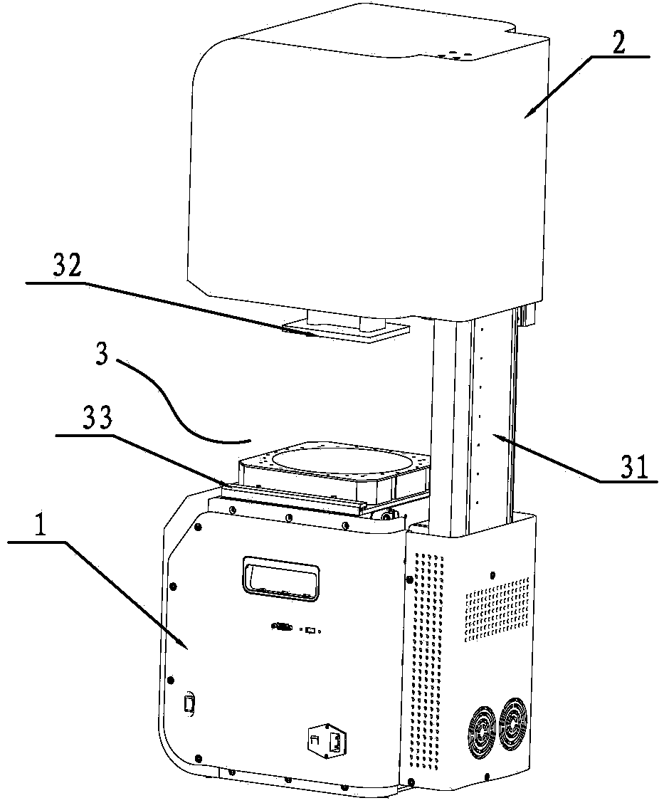
[0016] The oblique drawing assembly described in the present invention is applied to a 3D printing device, such as figure 1 As shown, the 3D printing device includes a base 1, an exposure mechanism and a control mechanism arranged in the base 1, a cover mechanism 2 and a printing mechanism 3 arranged on the base, wherein the printing mechanism 3 includes a module 31, The printing platform 32 that is slidably installed on the module 31, and the oblique drawing assembly 33 positioned at the bottom of the module 31; the module 31 is provided with a longitudinal thread, the printing platform 32 is connected with the thread, and the bottom of the thread is connected with the thread. The motors are connected, and the wire handle is driven to rotate by the wire handle motor, so that the printing platform 32 slides up and down on the module 31 . The exposure mechanism includes a projector, and the projector adopts a DLP projector.

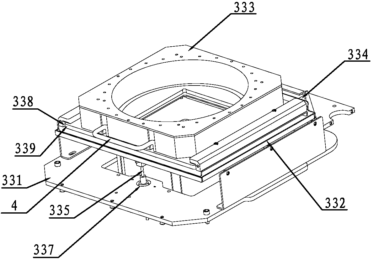
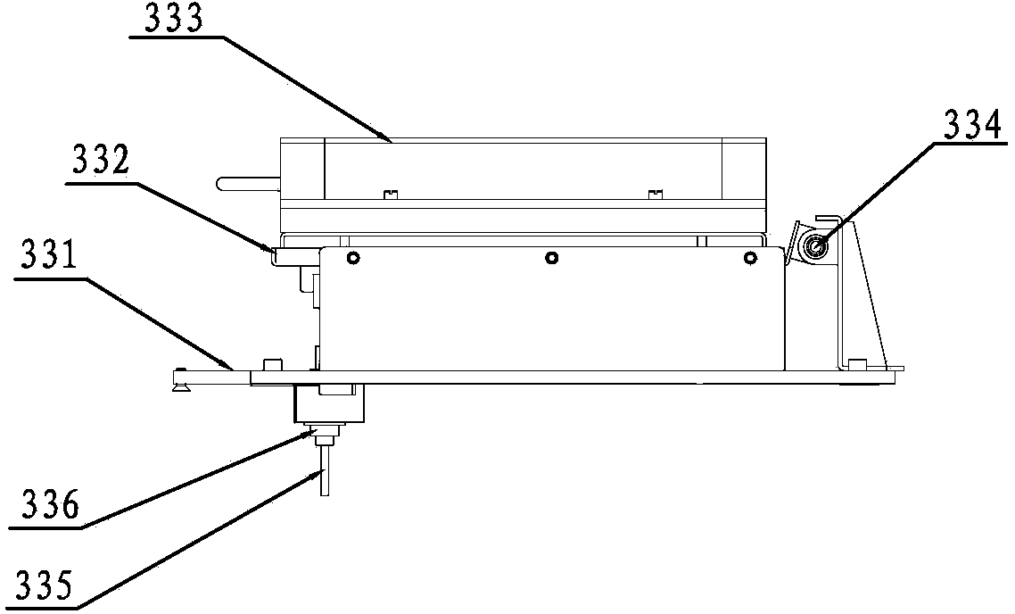
[0017] Such as Figure 2-3 As shown, the oblique d...


PUM


Abstract

The utility model discloses an inclined pulling assembly for a 3D printing device. The inclined pulling assembly comprises a mounting bracket and a hollow support frame movably connected with the mounting bracket through a connecting piece, wherein a resin frame used for accommodating a printing solution is mounted on the support frame; the bottom of the resin frame is a transparent bottom plate; a pull rod is further arranged at the bottom of the side edge, opposite to the connecting piece, of the support frame, and is connected with a driving motor; the support frame is enabled to rotate along the connecting piece through the ascending and descending of the pull rod. By adopting the inclined pulling assembly, a curing layer is completely separated from the bottom of the resin frame by pulling downwards on one side slowly, translation for increasing the plane area of the resin frame is not required, friction generated by translation is avoided, the service life of a thin film on the transparent bottom plate of the resin frame is greatly prolonged, and generally, one resin frame can be used for printing for 400,000-500,000 times.

Description

technical field [0001] The invention relates to a slanted component for a 3D printing device, which belongs to the technical field of printing equipment. Background technique [0002] A 3D printing device, also known as a three-dimensional printer, is a machine that uses cumulative manufacturing technology (that is, rapid prototyping technology). Its principle is to put data and raw materials into a 3D printer, and the machine builds products layer by layer according to the program. At present, the most common 3D printing device is SLA three-dimensional printing (also known as stereolithography, light modeling) using surface forming technology. The specific working principle is: the liquid tank is filled with liquid photocurable resin, It will solidify in the set area. When the molding starts, the working platform is on the liquid surface, and the distance between its lower surface and the upper surface of the transparent bottom plate at the bottom of the liquid tank is the ...

Claims


Application Information

Patent Timeline
Patent Type & Authority Applications(China)
IPC IPC(8): B29C67/00
Inventor 张靖金良金伟刚曾祥伟金杰陈明傅志强
Owner GUANGDONG SPRINTRAY 3D PRINTING TECH CO LTD
Learn More