
LED lamp for disaster relief and application thereof

A technology of LED lamps and LED light sources, which is applied to the layout of electric lamp circuits, lighting and heating equipment, electrical components, etc. It can solve problems such as lack of alarms, positioning, other functions cannot work, and power is exhausted, so as to extend the power usage time , Improve the effect of waiting for rescue and using for a long time

Inactive Publication Date: 2015-01-21
浙江中博光电科技有限公司
View PDF4 Cites 2 Cited by
  • Summary
  • Abstract
  • Description
  • Claims
  • Application Information

AI Technical Summary

Problems solved by technology

[0002] In mountainous areas or large disaster-stricken areas, communication lines, circuit interruptions, and mobile communication base station damage during the disaster are bystanders, especially when the disaster occurs at night, and the victims cannot judge their own location during the escape process. , and it is not clear where to transfer safely. In the case of damaged terrain, the external rescue team cannot know the specific location of the rescue area during the night march.
Therefore, it is necessary to guide the villagers through lights in the dark and indicate the direction for the rescue team. Although ordinary LED lights can also play an indicating role, they have a single function and do not have functions such as alarm and positioning. A variety of functions, due to the long lighting time at night, the power supply supports lighting and other functions at the same time, the power will be exhausted quickly, so that other functions cannot work, and it cannot solve the actual problems in the disaster area, and loses its huge use in emergency situations effect

Method used


Image

  • LED lamp for disaster relief and application thereof
  • LED lamp for disaster relief and application thereof

Examples


Embodiment Construction

[0025] The present invention will be described in further detail below in conjunction with the accompanying drawings and embodiments. The following embodiments are explanations of the present invention and the present invention is not limited to the following embodiments.

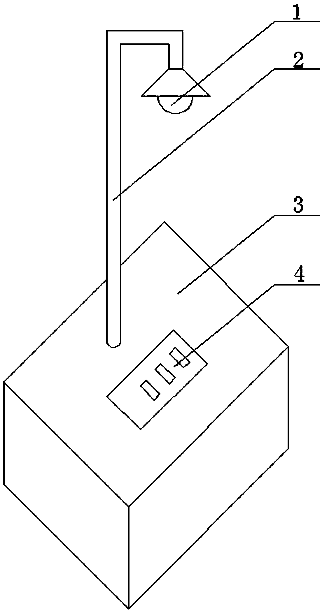
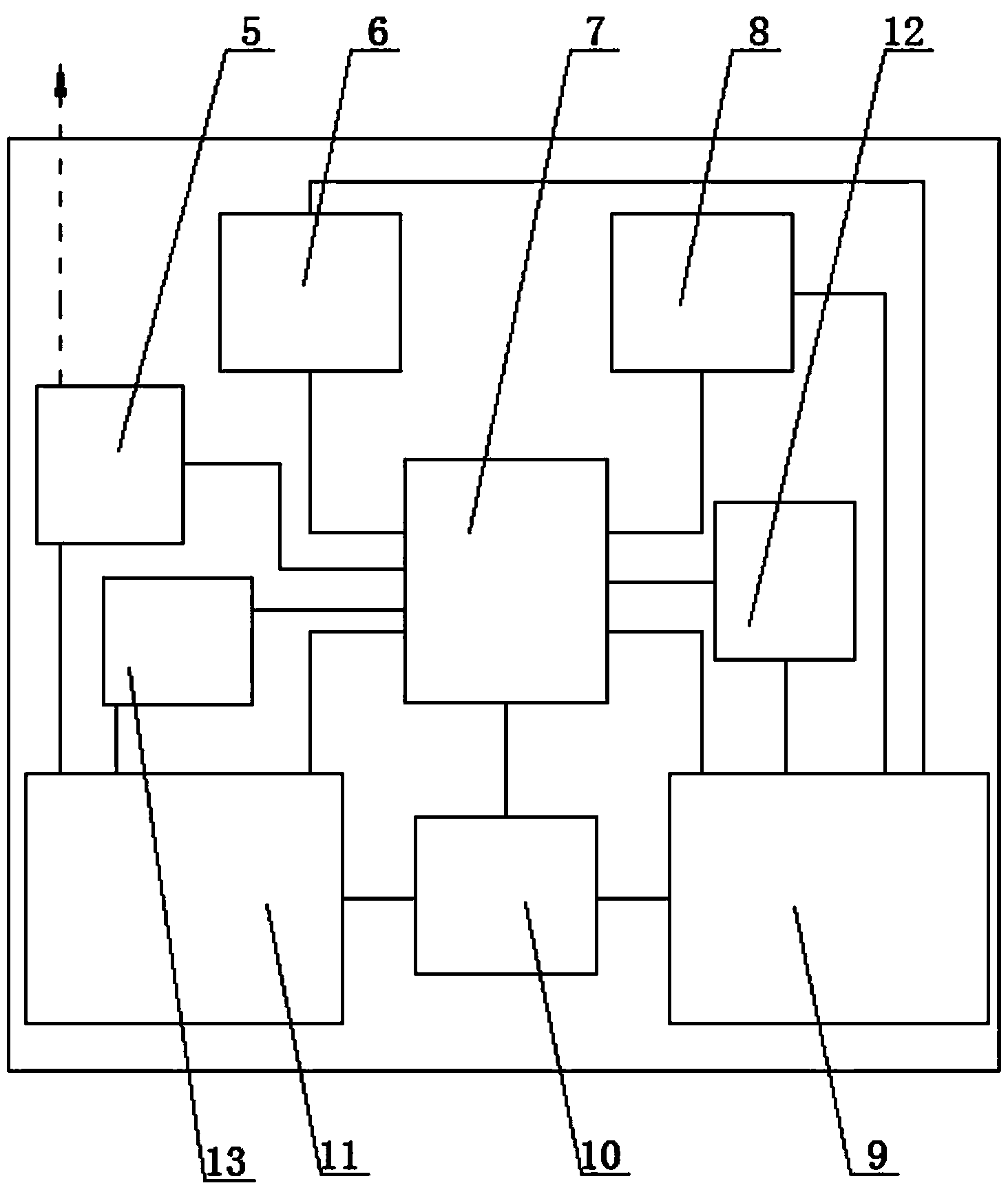
[0026] figure 1 and figure 2 A schematic diagram of the present invention is shown, a LED lamp for disaster relief, including a base 3, a connecting rod 2, an LED light source 1, a power supply, and is characterized in that it also includes an alarm 8, a control module 7, a control panel 4, and a charging module 10 , a wireless communication module 12, a positioning module 6, the LED light source 1 is installed on the top of the connecting rod 2, and the bottom end of the connecting rod 2 is connected to the base 3; the lighting power supply 11, the alarm power supply 9, the control module 7, The charging module 10, the wireless communication module 12, and the positioning module 6 are installed in the ba...


PUM


Abstract

The invention relates to an LED lamp and application of the LED lamp, in particular to an LED lamp for disaster relief and application of the LED lamp. The LED lamp for disaster relief comprises an LED light source, a power source, an alarm, an energy saving module, a charging module, a control module and a wireless communication module. The power source comprises an illumination power source and an alarm power source, the illumination power source is connected with the alarm power source, the LED light source is connected with the illumination power source, and the alarm, the wireless communication module, the control module, a locating module, the energy saving module and the charging module are connected with the alarm power source. The LED lamp provides illumination, guidance and alarming for disaster areas, when the electric quantity of the illumination power source is reduced, the LED lamp enters in an energy saving mode, power consumption is reduced, when the electric quantity of the alarm power source is reduced, the illumination power source can charge the alarm power source, normal work of the communication module, the locating module and the alarm module is guaranteed, the contact of the disaster areas and the outside can be kept smooth, and supports are provided for rescue.

Description

technical field [0001] The invention relates to an LED lamp and its application, in particular to an LED lamp for disaster relief and its application. Background technique [0002] In mountainous areas or large disaster-stricken areas, communication lines, circuit interruptions, and mobile communication base station damage during the disaster are near-sighted phenomena, especially when disasters occur at night, and the victims cannot judge their own location during the escape process. , It is not clear where to transfer safely. In the case of damaged terrain, the external rescue team cannot know the specific location of the rescue area during the night march. Therefore, it is necessary to guide the villagers through lights in the dark and indicate the direction for the rescue team. Although ordinary LED lights can also play an indicating role, they have a single function and do not have functions such as alarming and positioning. A variety of functions, due to the long ligh...

Claims


Application Information

Patent Timeline
Patent Type & Authority Applications(China)
IPC IPC(8): F21S9/02F21V23/00F21V31/00F21V33/00H05B37/02F21Y101/02
CPCF21S8/00F21S9/022F21V21/0832F21V21/092F21V23/00F21V31/005F21Y2101/00H05B47/10Y02B20/40
Inventor 洪宽王伟曹一男汪俊明
Owner 浙江中博光电科技有限公司
Learn More