
Telescopic lamp shell structure and LED ceiling lamp with same

A shell structure and telescopic lamp technology are applied in the direction of lampshade, parts of lighting devices, cooling/heating devices of lighting devices, etc., which can solve the inconvenience in the field of portable use of lamps, the inability to adjust the length and volume of lamps, and the structure of lamp shells. Can not carry out telescopic and other problems, to achieve the effect of saving packaging costs, saving packaging space, and being easy to carry

Inactive Publication Date: 2015-01-21
SHENZHEN OCEANS KING LIGHTING ENG CO LTD +1
View PDF0 Cites 1 Cited by
  • Summary
  • Abstract
  • Description
  • Claims
  • Application Information

AI Technical Summary

Problems solved by technology

[0002] The lamp housing structure of the existing lighting fixtures generally cannot be stretched or stretched only in the lamp housing with a fixed length. The length and volume of the lamp itself are fixed by design and cannot be adjusted later.
Therefore above-mentioned lamps and lanterns have many inconveniences in the field of portable use
At the same time, the existing lamps generally fix the light source in the lamp housing, which can only provide a predetermined light distribution effect, and cannot adjust the light output angle of the lamp in real time in the use occasion, and cannot meet the use occasions that require multiple light output effects.

Method used

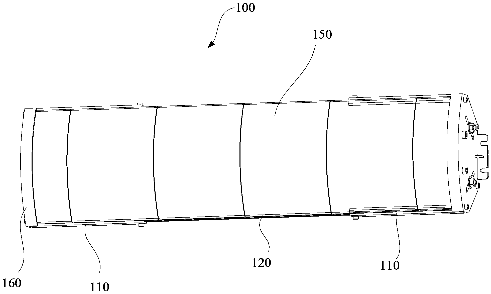
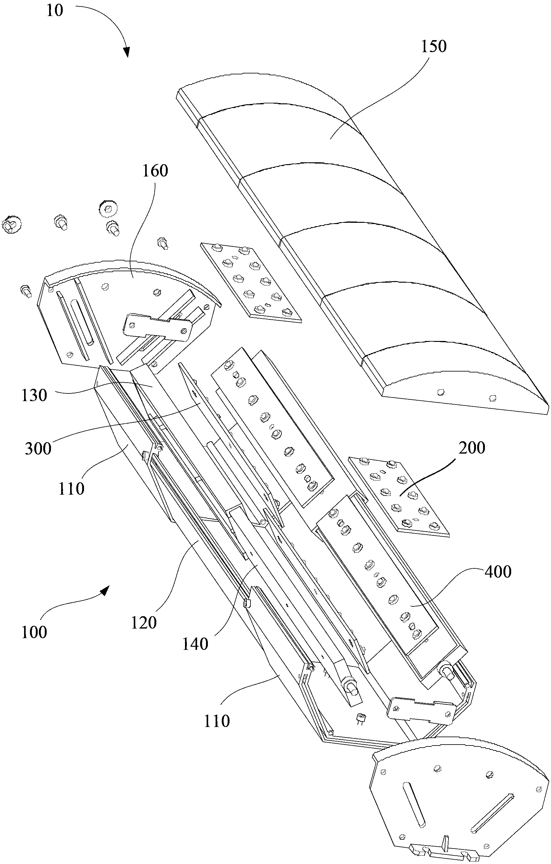
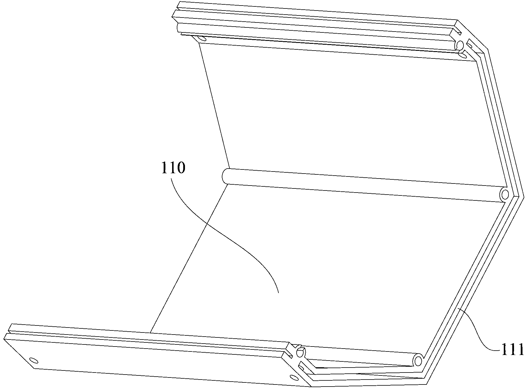

Image

  • Telescopic lamp shell structure and LED ceiling lamp with same
  • Telescopic lamp shell structure and LED ceiling lamp with same
  • Telescopic lamp shell structure and LED ceiling lamp with same

Examples


Embodiment Construction

[0041]In order to facilitate the understanding of the present invention, the present invention will be described more fully below with reference to the associated drawings. Preferred embodiments of the invention are shown in the accompanying drawings. However, the present invention can be embodied in many different forms and is not limited to the embodiments described herein. On the contrary, these embodiments are provided to make the understanding of the disclosure of the present invention more thorough and comprehensive.

[0042] It should be noted that when an element is referred to as being “fixed” to another element, it can be directly on the other element or there can also be an intervening element. When an element is referred to as being "connected to" another element, it can be directly connected to the other element or intervening elements may also be present. The terms "vertical," "horizontal," "left," "right," and similar expressions are used herein for purposes o...


PUM


Abstract

Disclosed is a telescopic lamp shell structure. The telescopic lamp shell structure comprises two main bottom shells, an auxiliary bottom shell, two end covers, two basic radiating boards, two movable radiating boards and a light permeable film assembly. Each main bottom shell is provided with a containing groove and a limiting portion. The bottoms of the main bottle shells are used for bearing first light source assemblies. The two ends of the auxiliary bottom shell are contained in the containing grooves in the two main bottom shells in a slidable mode, and the auxiliary bottom shell is provided with matching portions matched with the limiting portions. The two end covers are fixedly connected with openings in the ends of the two main bottom shells respectively. Each end cover is provided with a limiting groove. The two basic radiating boards and the two movable radiating boards are each provided with a double-screw bolt capable of penetrating through the corresponding limiting groove in a slidable mode. The double-screw bolts are connected with nuts in a screwed mode after penetrating through the limiting grooves in the end covers, so that the basic radiating boards and the movable radiating boards are fixed. The light permeable film assembly comprises a flexible light permeable film capable of being stretched and retracted after being stressed. The telescopic lamp shell structure is convenient to carry and has various light distribution effects. The invention further provides an LED ceiling lamp with the telescopic lamp shell structure.

Description

【Technical field】 [0001] The invention relates to a housing structure of a lamp, in particular to a retractable lamp housing structure and an LED dome light using the retractable lamp housing structure. 【Background technique】 [0002] The lamp housing structure of existing lighting fixtures generally cannot be stretched or stretched only in the lamp housing with a fixed length, and the length and volume of the lamp itself cannot be adjusted after the design is fixed. Therefore above-mentioned light fixture has inconvenience in portable use field more. At the same time, the existing lamps generally fix the light source in the lamp housing, which can only provide a predetermined light distribution effect, and cannot adjust the light emitting angle of the lamp in real time in the use occasion, and cannot meet the use occasions that require multiple light output effects. 【Content of invention】 [0003] In view of the above situation, it is necessary to provide a retractable l...

Claims


Application Information

Patent Timeline
Patent Type & Authority Applications(China)
IPC IPC(8): F21V3/02F21V17/10F21V29/74F21W101/04F21Y101/02F21W107/20
CPCF21V3/02F21V17/10F21W2107/20
Inventor 周明杰李鹏飞
Owner SHENZHEN OCEANS KING LIGHTING ENG CO LTD
Learn More