A system for transferring samples and precisely positioning samples for a sample analysis device
A sample analysis device and precise positioning technology, which is applied in the direction of analyzing materials, instruments, etc., can solve the problems of inaccurate positioning of sample containers, inability to realize fast switch positioning, complicated structure, etc., achieve accurate positioning function, reliable positioning, and simple implementation Effect
- Summary
- Abstract
- Description
- Claims
- Application Information
AI Technical Summary
Problems solved by technology
Method used
Image
Examples
Embodiment 1
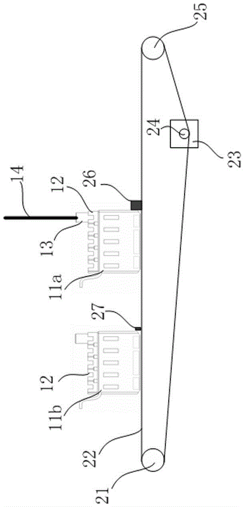
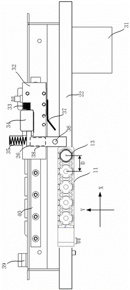
[0034] like Figure 1 to Figure 4 As shown, it is a schematic structural diagram of an embodiment of a system for transferring samples for a sample analysis device and accurately positioning the samples provided by the present invention. mechanism, holding mechanism, guide mechanism, release mechanism 39 and blocking mechanism 27. Wherein: the conveying device includes a flat belt 22, a driving pulley 24, a driven pulley 21\25 and a motor 23; the moving mechanism includes a moving block 32 and a guide rail 40, and the guide rail 40 is arranged parallel to the traveling direction of the sample holder strip 11 (ie, the X-axis direction). , the movable block 32 is set on the guide rail 40; the positioning mechanism includes the positioning block 26, the guide rail 38 and the elastic member 35, the guide rail 38 is horizontally arranged on the movable block 32 in a manner perpendicular to the guide rail 40 (ie along the Y-axis direction), and the positioning block 26 is arranged ...
Embodiment 2
[0044] The positioning block used in the system for transferring the sample for the sample analysis device and accurately positioning the sample provided by the present invention can also adopt other structural forms different from the first embodiment, such as passing one end of the positioning block through a horizontal rotation axis arranged in the horizontal direction It is fixedly connected with the movable block, so that the other end of the positioning block is in the positioning state against the sample holder strip. see Figure 5 As shown, the positioning block 26b in this embodiment is rotatable around the rotation axis 38b, and the rotation axis 38b is arranged along the X axis, so as to realize the retraction of the positioning block 26b in the direction of the Y axis. Also after the guide wheel 36b is constrained by the guide plate, the positioning block 26b is rotated and held by the holding block. In the initial position, the holding block is released by the rel...
Embodiment 3
[0046] The positioning block used in the system for transferring the sample for the sample analysis device and accurately positioning the sample provided by the present invention can also adopt other structural forms that are different from the first and second embodiments. For example, one end of the positioning block is passed through a vertical The vertical rotating shaft arranged in the vertical direction is fixedly connected with the movable block, so that the other end of the positioning block is in a positioning state against the sample holder strip. like Image 6 As shown, the positioning block 26c and the holding block 34c are also fixed on the movable block 32. The positioning block 26c can rotate around the rotation axis 38c, and the rotation axis 38c and the Z axis are parallel. Under the action of the elastic force of the compression spring 35c or the torsion spring, and other constraints (not shown), the positioning block 26c can maintain the positioning state. ...
PUM
 Abstract
Description
Claims
Application Information
 - R&D
- Intellectual Property
- Life Sciences
- Materials
- Tech Scout
- Unparalleled Data Quality
- Higher Quality Content
- 60% Fewer Hallucinations
Browse by: Latest US Patents, China's latest patents, Technical Efficacy Thesaurus, Application Domain, Technology Topic, Popular Technical Reports.
© 2025 PatSnap. All rights reserved.Legal|Privacy policy|Modern Slavery Act Transparency Statement|Sitemap|About US| Contact US: help@patsnap.com


