
A voltage regulation circuit and array substrate

A voltage regulation circuit and voltage regulation technology, applied to electrical components, conversion equipment without intermediate conversion to AC, output power conversion devices, etc., can solve the problem of long consumption, low boost efficiency, and difficulty in accurately controlling the output voltage Boost multiples and other issues to achieve high voltage regulation efficiency, simple structure, increase the speed of opening and closing

Active Publication Date: 2017-12-08
BOE TECH GRP CO LTD +1
View PDF8 Cites 0 Cited by
  • Summary
  • Abstract
  • Description
  • Claims
  • Application Information

AI Technical Summary

Problems solved by technology

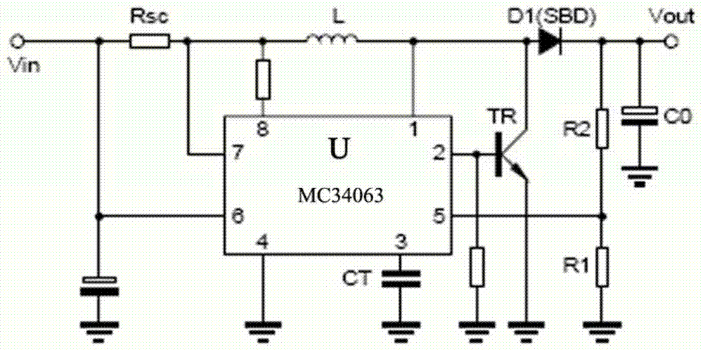
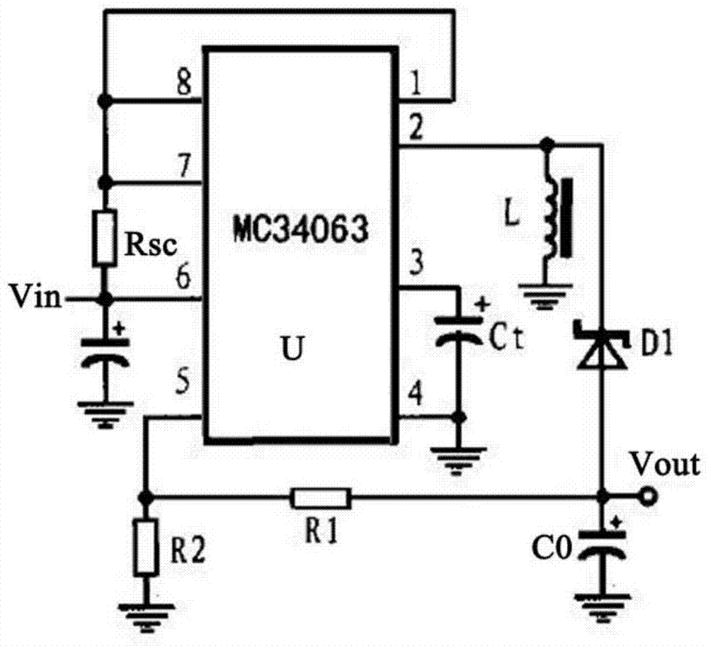
[0005] In the above-mentioned Boost and Buck circuits, the inductor L stores energy in the first stage, so that the voltage output terminal Vout can output a high voltage in the second stage, so that it takes a long time to make the voltage output terminal Vout to Output a predetermined high voltage externally, that is to say, its boosting efficiency is low; in addition, in the above-mentioned Boost and Buck circuits, the voltage value output from the output voltage terminal Vout is adjusted by controlling the feedback resistors R1 and R2. Such adjustment It is difficult to accurately control the boost multiple of the output voltage

Method used


Image

  • A voltage regulation circuit and array substrate
  • A voltage regulation circuit and array substrate
  • A voltage regulation circuit and array substrate

Examples


Embodiment Construction

[0036] Specific embodiments of the present invention will be described in detail below in conjunction with the accompanying drawings. It should be understood that the specific embodiments described here are only used to illustrate and explain the present invention, and are not intended to limit the present invention.

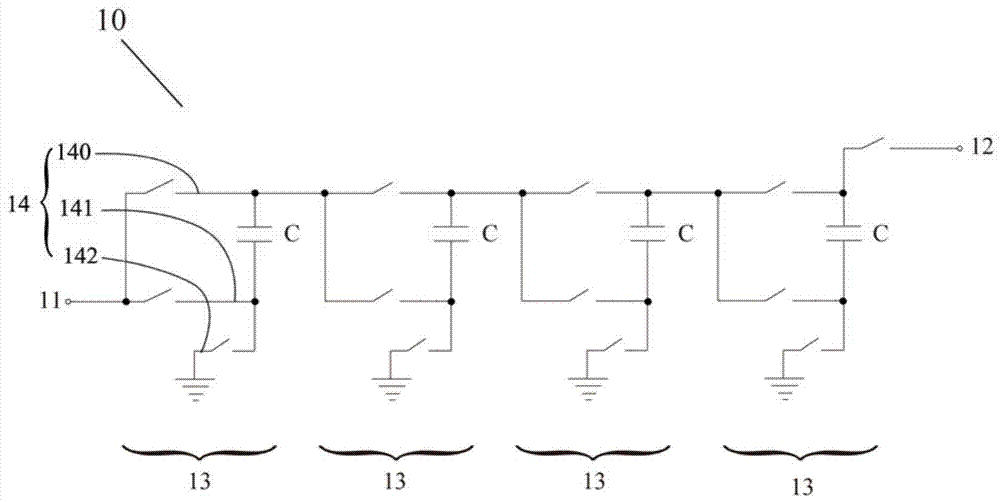
[0037] image 3 It is a schematic circuit diagram of the first embodiment of the voltage regulation circuit provided by the present invention. Such as image 3 As shown, the voltage regulation circuit 10 includes an input terminal 11, a first output terminal 12, a multi-stage first voltage regulation module 13 and a control unit (not shown in the figure). Wherein, the input terminal 11 is used for introducing the reference voltage Vr, and the first output terminal 12 is used for outputting the first voltage Vgh regulated by the voltage regulating circuit 10 . The first voltage regulating module 13 of each stage includes a bootstrap capacitor C and a selection...


PUM


Abstract

The invention relates to a voltage regulator circuit and an array substrate. The voltage regulator circuit comprises an input end, a first output end, at least one stage of first pressure regulating module and a control unit; the input end is used for leading in the reference voltage, the first output end is used for outwards outputting the first voltage, each stage of first pressure regulating module comprises a bootstrap capacitor and a selection circuit, each selection circuit is used for charging the first end of the corresponding bootstrap capacitor in the first stage and charging the second end of the corresponding bootstrap capacitor in the second stage, and the voltage at the first ends of the bootstrap capacitors is regulated through the bootstrap effect; at least the selection circuit of the lowest stage of the first pressure regulating module is connected with the input end; at least the first end of the bootstrap capacitor of the highest stage of the first pressure regulating module is connected with the first output end, and a first output switch is arranged on a connecting line of the bootstrap capacitor and the first output end; on and off of the first output switch are controlled through a control unit. The voltage regulator circuit has the high voltage regulation efficiency. Meanwhile, compared with a Boost circuit in the prior art, the structure of the voltage regulator circuit is simpler.

Description

technical field [0001] The present invention relates to the technical field of DC conversion of voltage and liquid crystal display, in particular, to a voltage regulating circuit and an array substrate. Background technique [0002] In a thin film transistor liquid crystal display (TFT LCD), the thin film transistor (TFT) is generally turned on and off when the TFT LCD displays each frame, and a voltage is applied to the pixel electrode corresponding to each TFT to make the corresponding pixel display the corresponding brightness. Specifically, the turn-on voltage of TFT is generally 12-35V, the turn-off voltage is generally -6--15V, and the reference voltage provided by the driver chip is generally 2.5-3.3V, therefore, the reference voltage needs to be boosted and reversed. Get the turn-on and turn-off voltages of the TFT. In the prior art, the reference voltage is generally boosted by a Boost circuit to reach the turn-on voltage of the TFT; the reference voltage is booste...

Claims


Application Information

Patent Timeline
Patent Type & Authority Patents(China)
IPC IPC(8): H02M3/07
CPCH02M3/073
Inventor 刘宝玉
Owner BOE TECH GRP CO LTD
Learn More