Flyback converter and control method of flyback converter
A flyback converter and control method technology, applied in control/regulation systems, DC power input conversion to DC power output, instruments, etc., can solve the problem of low utilization rate of magnetic core, small negative excitation current, lower overall efficiency, etc. problem, to achieve the effect of reducing EMI interference, reducing the volume of the magnetic core, and increasing the utilization rate
- Summary
- Abstract
- Description
- Claims
- Application Information
AI Technical Summary
Benefits of technology
Problems solved by technology
Method used
Image
Examples
Embodiment 1
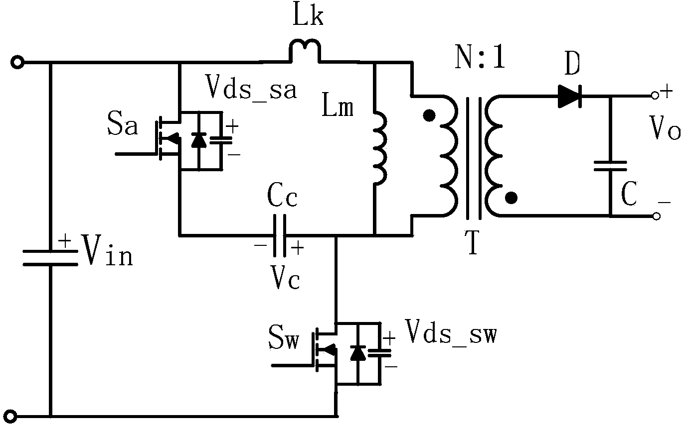
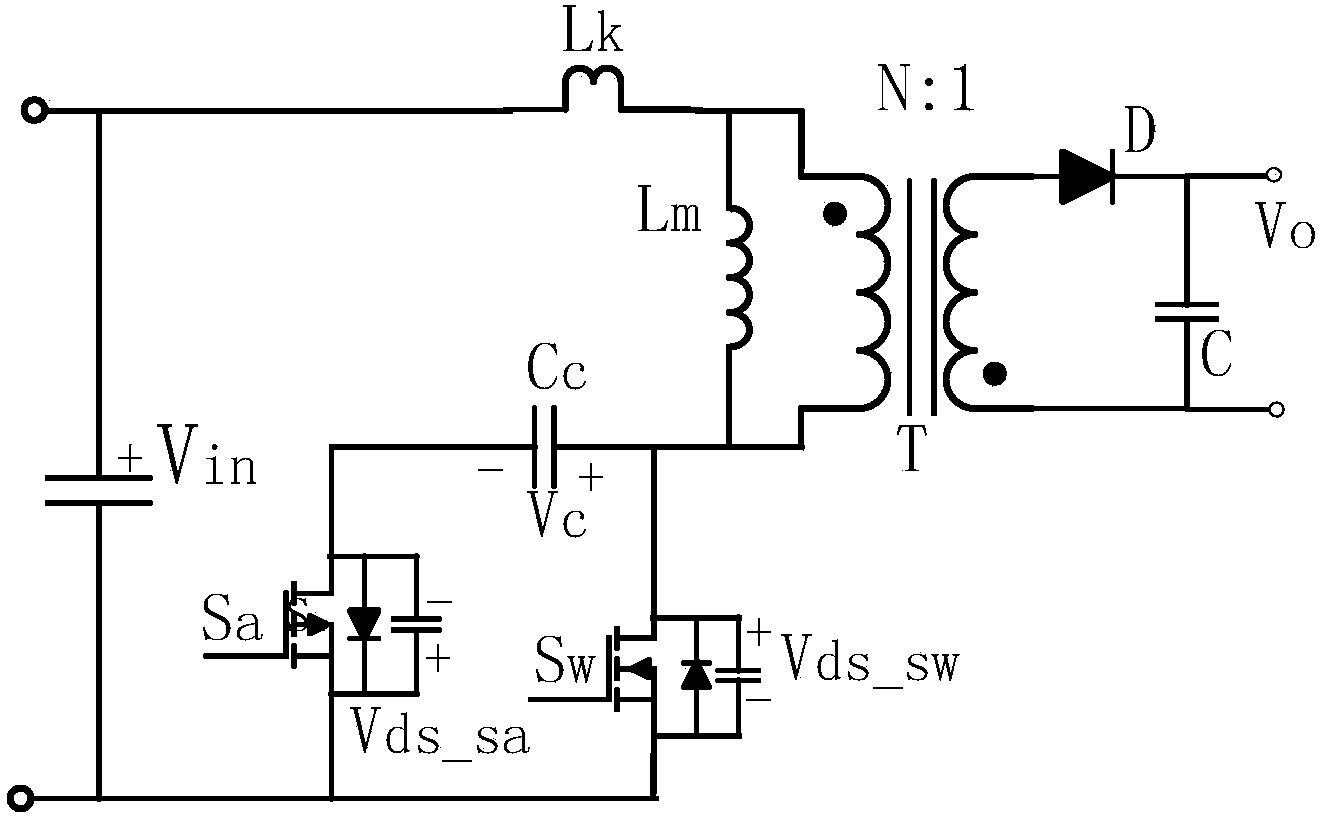
[0043] A control method of a flyback converter of the present invention comprises the following steps,
[0044] Judging whether the converter is working in a small load state,
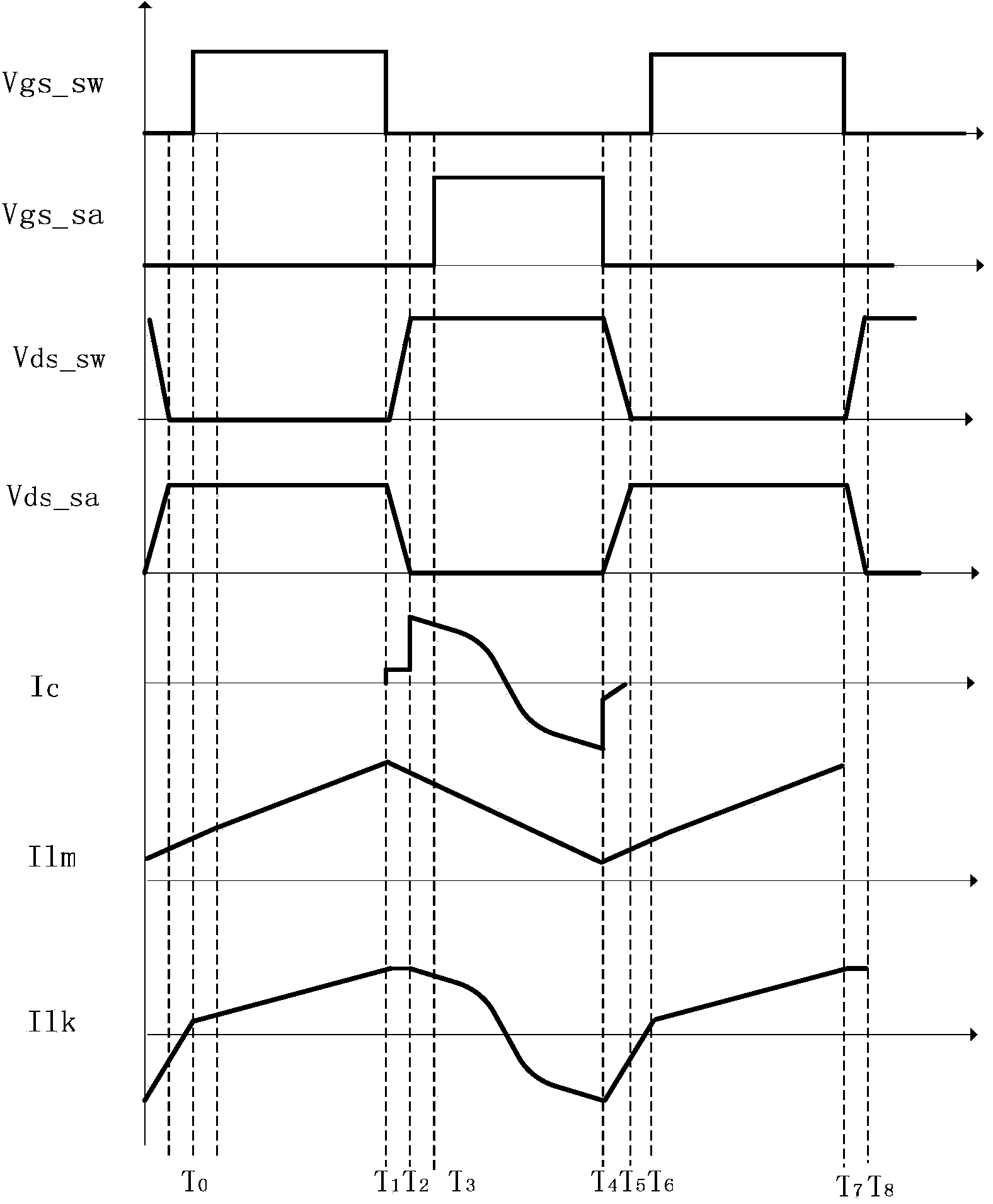
[0045] If so, control the clamping module to enter a non-complementary working mode. The non-complementary working mode is to send a narrow pulse control signal before the main switch is turned on and before the nanosecond-level dead time is left, and the rising edge of the narrow pulse Drive the conduction of the clamp switch tube, and control the turn-off of the clamp switch tube by the falling edge of the narrow pulse; after the clamp switch tube is turned off and there is a nanosecond dead time, control the main switch tube to turn on ;
[0046] If not, control the clamping module to enter the complementary working mode, the complementary working mode is to generate a wide pulse driving signal that is complementary to the main switching tube and has a nanosecond dead time, so as to be driven by th...
Embodiment 2
[0062] Figure 7 Shown is the circuit schematic diagram of the detection control circuit of the flyback converter in the second embodiment of the present invention, the detection feedback voltage VFB, the feedback voltage VFB changes with the load, the greater the load, the higher the voltage, at different VFB voltages Next, the voltage-controlled constant current source generates a changing current to charge the capacitor and generates a changing driving pulse width signal to output to the clamping switch tube. When the clamping switch tube is turned off, it outputs a driving signal to the main switch tube Sw. When entering The next cycle is repeated to realize that the conduction time of the clamp switch tube is different under different loads, and to realize that the source-clamp flyback converter operates in different operating modes under different loads.
[0063] Figure 7 Shown is the circuit schematic diagram of the detection control module of the flyback converter in...
Embodiment 3
[0066] Figure 8 Shown is the circuit schematic diagram of the detection control module of the flyback converter in the third embodiment of the present invention, the detection feedback voltage VFB, the feedback voltage VFB changes with the load, the greater the load, the higher the voltage, at different VFB voltages Next, the voltage-controlled constant current source generates a changing current to charge the capacitor and generates a changing driving pulse width signal to output to the clamping switch Sa. When the main switching tube Sw is turned off, a dead time is generated. When the main switching tube Sw is turned off And after the dead time is over, the clamp switch Sa is turned on, and the conduction time of the clamp switch Sa is adjusted by adjusting the dead time after the main switch Sw is turned off, so as to realize the active clamp flyback converter In different working modes under different loads.
[0067] Figure 8Shown is the circuit principle diagram of t...
PUM
 Abstract
Description
Claims
Application Information
 - R&D
- Intellectual Property
- Life Sciences
- Materials
- Tech Scout
- Unparalleled Data Quality
- Higher Quality Content
- 60% Fewer Hallucinations
Browse by: Latest US Patents, China's latest patents, Technical Efficacy Thesaurus, Application Domain, Technology Topic, Popular Technical Reports.
© 2025 PatSnap. All rights reserved.Legal|Privacy policy|Modern Slavery Act Transparency Statement|Sitemap|About US| Contact US: help@patsnap.com


