
pressure limiting valve

A pressure-limiting valve and valve technology, applied in control valves, safety valves, balance valves, etc., can solve problems such as damage and failure of pressure-limiting valves, and achieve the effect of weakening axial movement and high antifouling ability

Inactive Publication Date: 2017-03-01
VOSS AUTOMOTIVE
View PDF8 Cites 0 Cited by
  • Summary
  • Abstract
  • Description
  • Claims
  • Application Information

AI Technical Summary

Problems solved by technology

[0003] In practice, especially with valves with spherical valve bodies as described in German patent application DE 43 11 856 A1, it has been shown that under certain operating conditions the pressure limiting valve can be damaged, or even case of total failure

Method used


Image

  • pressure limiting valve
  • pressure limiting valve
  • pressure limiting valve

Examples


Embodiment Construction

[0076] For the following description, it needs to be emphasized that the present invention is not limited to the embodiments, and therefore is not limited to all or more features in the described combination of features, more precisely, each individual in any embodiment A sub-feature still has the meaning according to the invention, whether alone or in combination with any feature in another embodiment, separately from all other sub-features described in combination.

[0077] In the different drawings, the same components are provided with the same reference numerals and are therefore usually only described once.

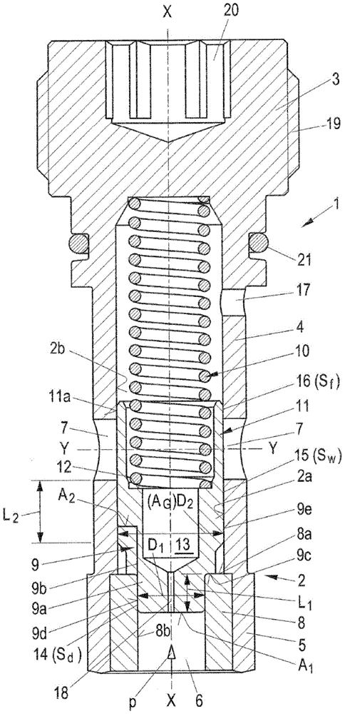
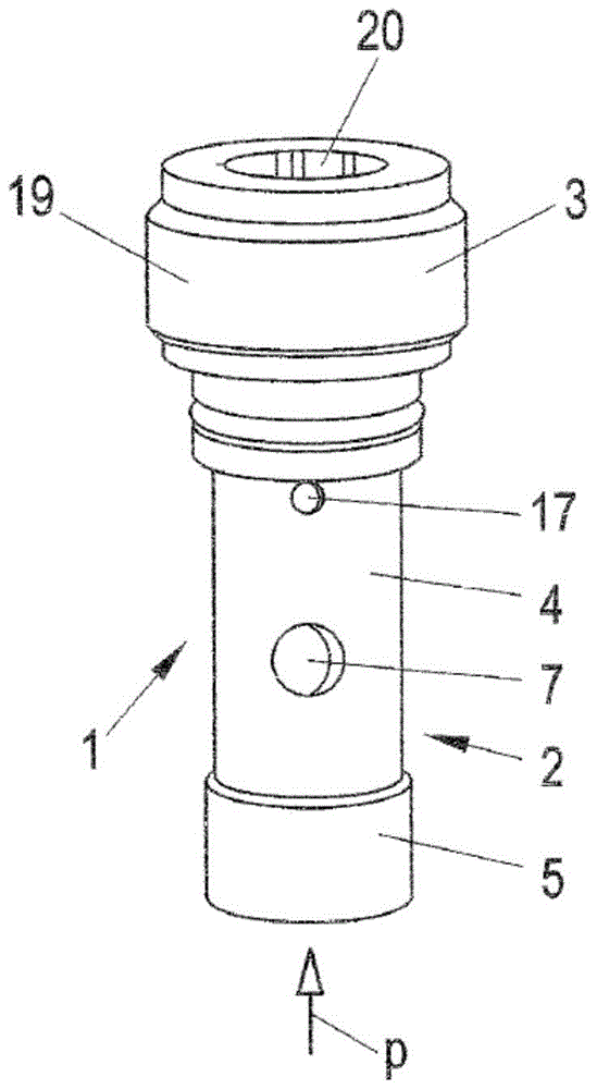
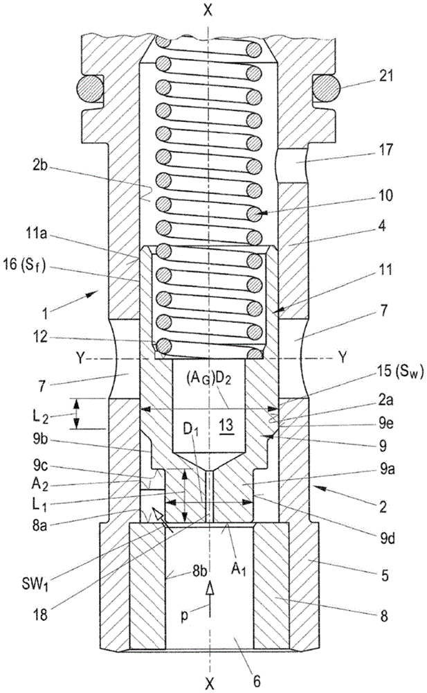
[0078] as first in figure 1 and figure 2 As shown in the course, the Figure 3 to Figure 5 as well as Figure 7 It can also be seen in , that the pressure limiting valve 1 according to the invention can be installed in particular in the return line of a common rail system of an internal combustion engine, which has a valve housing 2 . Valve housing 2 includes h...


PUM


Abstract

The invention relates to a pressure limiting valve (1), in particular for a return line installed in a common rail system of an internal combustion engine, having a valve housing (2) with a housing top (3) and a hollow cylindrical housing housing (4), wherein there is an axial inlet (6) in the valve seat (5) of the valve housing (2) and at least one axially spaced from the inlet (6) open outlet (7), where in the valve seat (5) the inner seat (8) for the valve body (9) is connected to the inlet (6) and between the valve body (9) and the return spring ( Between 10) there is an axially movable valve piston (11), the return spring (10) generating a return force against the pressure (p) acting on the inlet (6). In order to improve the functional characteristics of the valve (1), the invention proposes that the valve body (9) is constructed as a multi-stage piston, in its first step (9a) it has on its surface facing the inlet (6) A first surface (A1) capable of bearing pressure (p) in the axial direction and a first axial length (L1) through which, in a closed position, the multistage The piston forms a circumferentially extending first throttling gap (14) with its outer surface (9d) and the inner surface (8b) of the valve seat (8), and in the second step (9b) of the multi-stage piston, its has a second surface (A2) capable of bearing pressure (p) in the axial direction (X‑X), which together with the first surface (A1) constitutes the total bearing surface (AG), and, at On the entire second axial length (L2) of the second step (9b), a circumferential gap is formed between the outer surface (9e) of the multistage piston (9) and the inner surface (2a) of the housing cover (4). An extended second throttle gap (15) having a second gap width (Sw).

Description

technical field [0001] The invention relates to a pressure limiting valve, in particular a pressure limiting valve installed in a return line of a common rail system of an internal combustion engine, which has a valve housing with a housing top and a hollow cylindrical housing An outer casing, wherein an axial inlet and at least one radial outlet axially spaced from this inlet are present in the valve seat (Ventilfuβ) of the valve housing, and in which there is a The inner valve seat is connected to the inlet, and an axially movable valve piston is arranged between the valve body and a return spring which generates a return force against the pressure acting on the inlet. Background technique [0002] Pressure limiting valves of this type are used in the fuel return line of so-called common rail injection systems of internal combustion engines. During common rail injection (also known as accumulator injection), the high pressure pump pressurizes the fuel to a high pressure l...

Claims


Application Information

Patent Timeline
Patent Type & Authority Patents(China)
IPC IPC(8): F02M63/00F02M37/00F16K17/04G05D7/01F16K17/08
CPCF02M63/005F02M63/0056F16K15/025F16K17/065Y10T137/7738F02M37/00F02M63/00F16K17/04F16K17/08Y02T10/12F02M37/0029F16K17/0466F16K17/082
Inventor 乌尔里希·埃尔布
Owner VOSS AUTOMOTIVE
Learn More