Connection structure for printed circuit boards, electronic device, and servomotor

A printed substrate and connection structure technology, applied in the structural connection of printed circuits, printed circuits, printed circuits, etc., to avoid stress and reduce the number of components

Active Publication Date: 2015-01-21
NSK LTD
View PDF13 Cites 0 Cited by
  • Summary
  • Abstract
  • Description
  • Claims
  • Application Information

AI Technical Summary

Problems solved by technology

However, there are cases where the sub-printed board must be arranged parallel to the front panel in order to arrang

Method used


Image

  • Connection structure for printed circuit boards, electronic device, and servomotor
  • Connection structure for printed circuit boards, electronic device, and servomotor
  • Connection structure for printed circuit boards, electronic device, and servomotor

Examples


Example Embodiment

[0055] Hereinafter, an embodiment of the present invention will be described, but the present invention is not limited to the embodiment.

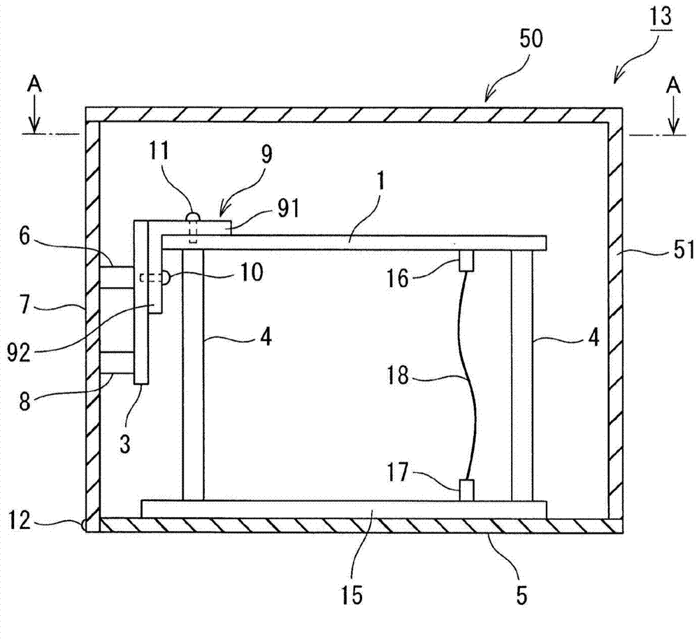
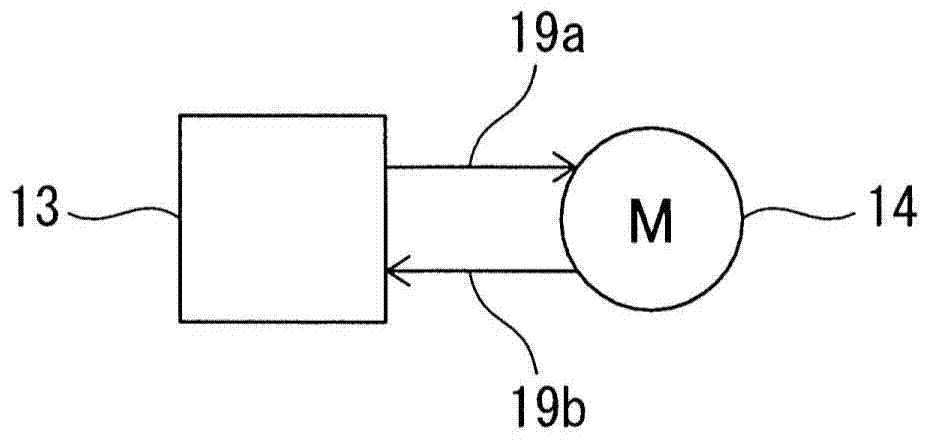
[0056] The electronic device 13 of this embodiment has a housing 50 , a first printed board 1 , a second printed board 2 , and a third printed board 15 . These printed circuit boards 1 , 2 , and 15 are arranged in a casing 50 . The casing 50 has a front panel 7 and a bottom panel 5 which are formed of separate components. The front panel 7 and the base plate 5 are perpendicular to each other. The front panel 7 and the bottom panel 5 are fixed together by small screws 12 inserted through the front panel 7 .

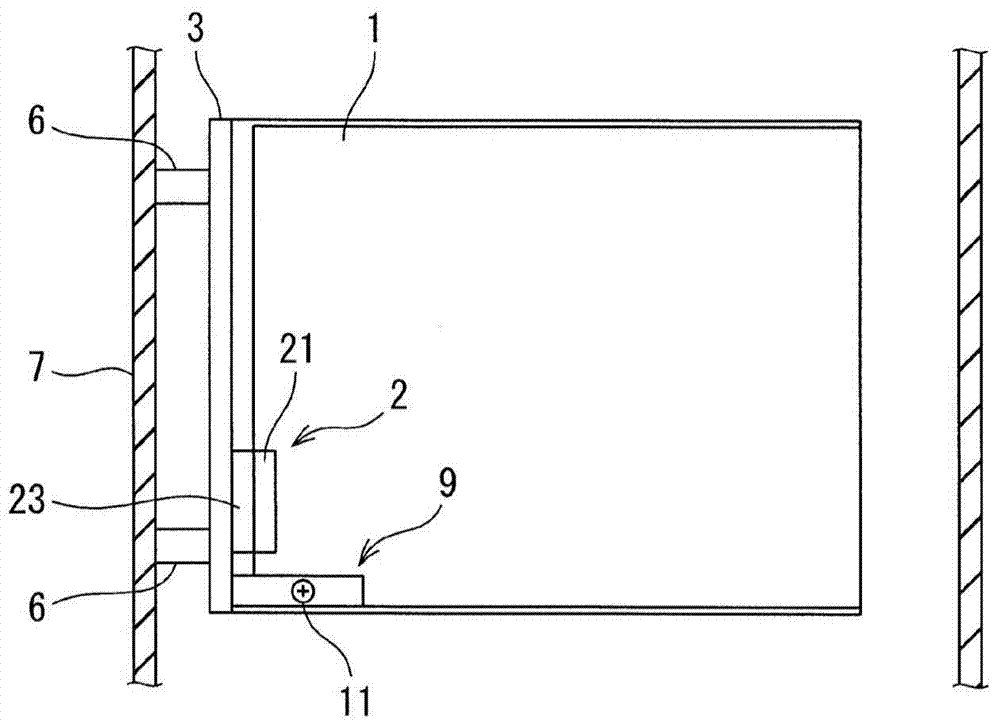
[0057] The second printed circuit board 3 is arranged parallel to the front panel 7 and fixed with respect to the front panel 7 using spacers (second spacers) 6 , 8 .

[0058] The first printed circuit board 1 and the third printed circuit board 15 are arranged perpendicular to the front panel 7 . The third printed circuit board 15...


PUM


Abstract

In this connection structure for printed circuit boards, a first and second printed circuit board (1, 3), which are disposed perpendicularly to one another and are electrically connected together, are secured within a casing (50). The electrical wiring of the first printed circuit board (1) and the electrical wiring of the second printed circuit board (3) are connected by connectors (21, 23). Both printed circuit boards (1, 3) are secured by means of an L-shaped fitting (9) near the connector connecting section (2) of both printed circuit boards (1, 3).

Description

technical field [0001] The present invention relates to a connection structure of printed substrates (a structure in which multiple printed substrates arranged perpendicular to each other and electrically connected are fixed in a housing), an electronic device having the connection structure (a plurality of printed substrates arranged perpendicular to each other and electrically connected The electronic device fixed in the housing in the state), and the servo motor equipped with the electronic device. Background technique [0002] With the increase in density of electronic devices in recent years, in an electronic device used as a control device for a servo motor, not only a plurality of printed circuit boards are arranged in parallel to each other, but also a plurality of printed circuit boards are arranged in a direction perpendicular to each other. is increasing. [0003] For example, in a control device for a servo motor, a power amplifier board and a control board as a...

Claims


Application Information

Patent Timeline
IPC IPC(8): H05K1/14H05K7/14
CPCH05K1/14H05K7/1432H05K3/366H05K1/144H05K2201/042H05K2201/10409H05K7/14322
Inventor 渡部芳幸小山睦杉浦创
Owner NSK LTD
Why Eureka
Try Eureka