Body surface location method and system

A positioning method and body surface technology applied in the medical field to achieve the effects of avoiding X-ray radiation, improving health and saving X-ray dose

Inactive Publication Date: 2015-01-28
NEUSOFT MEDICAL SYST CO LTD
View PDF0 Cites 8 Cited by
  • Summary
  • Abstract
  • Description
  • Claims
  • Application Information

AI Technical Summary

Problems solved by technology

[0004] In order to solve the existing technology, the embodiment of the present invention provides a body surface positioning method and system, which can reduce the damage caused by harmful radiation such as X-rays to the human body when the body surface is positioned on the human body

Method used


Image

  • Body surface location method and system
  • Body surface location method and system
  • Body surface location method and system

Examples


Embodiment 1

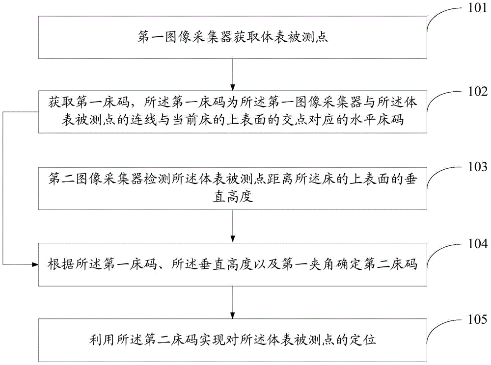
[0037] see figure 1 , which is a flow chart of Embodiment 1 of a body surface positioning method provided by the present invention.

[0038] The body surface positioning method provided in this embodiment includes the following steps:

[0039] Step 101: the first image collector acquires measured points on the body surface.

[0040] The body surface measured point in the present invention refers to the point on the side profile of the human body lying on the bed.

[0041] In order to obtain the measured points on the body surface clearly and directly, the position of the first image collector should be set vertically above the surface of the bed. The specific position depends on the actual situation and is not specifically limited in the present invention. In this embodiment, in order to be applicable to most situations, the first image collector is arranged directly above the centerline of the bed, and the centerline of the bed is parallel to the long side of the bed and di...

Embodiment 2

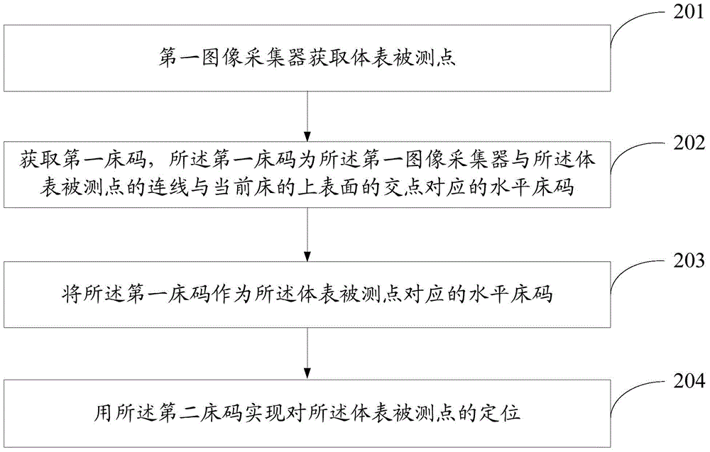
[0051] In the first method embodiment, it is not limited whether the first included angle is less than 90 degrees or equal to 90 degrees, but this embodiment discloses the body surface positioning method in these two cases.

[0052] When the first included angle is 90 degrees, see figure 2 , the body surface positioning method includes the steps of:

[0053]Step 201: The first image collector acquires measured points on the body surface.

[0054] Step 202: Obtain the first bed code, which is the horizontal bed code corresponding to the intersection of the line connecting the first image collector and the measured point on the body surface with the upper surface of the current bed.

[0055] Step 203: Use the first bed size as the horizontal bed size corresponding to the measured point on the body surface.

[0056] Since the first included angle is 90 degrees, the horizontal bed code corresponding to the intersection point between the line connecting the first image collector...


PUM


Abstract

An embodiment of the invention discloses a body surface location method. The body surface location method includes that a first image collector acquires a test point of the body surface; a first bed size is acquired, to be specific, the first bed size is s horizontal bed size corresponding to an intersection point of the upper surface, of a current bed, and a connecting line, of the first image collector and the test point of the body surface; a second image collector measures the vertical distance from the test point of the body surface to the upper surface of the bed; a second bed size is determined according to the first bed size; the vertical distance and a first inclined angle, to be specific, the second bed size is the horizontal bed size of the test point of the body surface, and the first inclined angle is between the connecting line, of the first image collector and the test point of the body surface, and a straight line, formed by projecting the connecting line to the upper surface of the bed; the test point of the body surface is located by the second bed size. An embodiment of the invention further discloses a body surface location system. By the use of the body surface location method and system, X-ray radiation which is caused by human body surface location and which brings damages to patients is avoided, health of the patients is improved, and X-ray dosage is reduced.

Description

technical field [0001] The invention relates to the medical field, in particular to a body surface positioning method and system. Background technique [0002] In the process of clinical treatment, it is often necessary to locate the body surface of the human body. At present, CT scanning is usually used for body surface positioning. CT scanning refers to scanning a layer of a certain thickness of a certain part of the human body with an X-ray beam. The X-rays that pass through this layer are received by the detector, converted into visible light, converted from photoelectric to electrical signals, and then converted by analog / digital. The converter converts it into a digital signal and inputs it to a computer for processing. [0003] However, as X-rays irradiate the human body, the cells may be inhibited, destroyed or even necrotic, resulting in varying degrees of physiological, pathological and biochemical changes in the body, thus causing harm to the human body, such as ...

Claims


Application Information

Patent Timeline
Patent Type & Authority Applications(China)
IPC IPC(8): A61B6/03
CPCA61B6/032A61B6/488A61B6/5211A61B6/544A61B6/545G16H50/20G01B11/26G01B11/0608
Inventor 闫刚
Owner NEUSOFT MEDICAL SYST CO LTD
Why Eureka
Try Eureka