Fire Hose Cleaning Equipment
A technology for fire hoses and cleaning equipment, applied in fire rescue and other directions, can solve the problems of large waste of water resources and inability to clean fire hoses, and achieve the effects of saving labor, reducing water consumption and improving cleanliness
- Summary
- Abstract
- Description
- Claims
- Application Information
AI Technical Summary
Problems solved by technology
Method used
Image
Examples
Embodiment 1
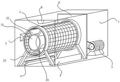
[0030] Embodiment one, refer to figure 1 , the fire hose cleaning equipment of this embodiment includes a box body 1 and a drum 2 which are horizontally arranged in the box body 1 through a drum frame 23, the drum 2 is rotationally connected with the drum frame 23, and a motor 3 for controlling the rotation of the drum 2, the drum 2 There is an inner cylinder 21 inside, and a partition 22 is arranged between the inner cylinder 21 and the drum 2 to divide the drum 2 into 3-5 compartments 24 for holding fire hoses, and the wall of the drum 2 is a grid mesh , the outside of the drum 2 is provided with several high-pressure nozzles 4 for cleaning fire hoses.
[0031] The present invention is simple in structure, and the drum 2 is designed to have a structure with multiple compartments 24, which solves the drawbacks in the prior art that it is impossible to clean multiple fire hoses. The water column flushes through the grille on the surface of the drum 2 to the fire hose inside t...
Embodiment 2
[0049] Embodiment 2: The difference from Embodiment 1 is that the inner cylinder 21 and the partition 22 in Embodiment 2 are all in the shape of a grid. The water of the washing liquid and the hot air at the hot air holes can enter other compartments 24 through the grid holes.
Embodiment 3
[0050] Embodiment 3: The difference from Embodiment 2 is that the inner cylinder 21 in Embodiment 3 is not grid-shaped, but the outer wall of the inner cylinder 21 is provided with high-pressure nozzles 4 and water pipes. Such a design can be faster. Clean the fire hose.
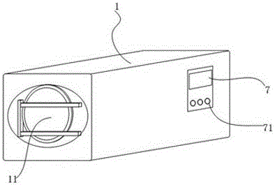
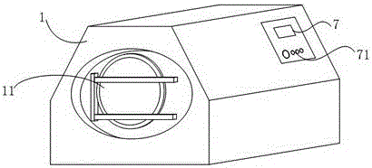
[0051] exist figure 1 , image 3 , Figure 4 , in order to avoid too many lines, resulting in unclear diagrams, so the surface that can be observed through the grid is not drawn. In addition, the hot air blower, delivery box, high-pressure water pump and solenoid valve are conventional design components , so it is not shown in the figure.
PUM
 Abstract
Description
Claims
Application Information
 - R&D
- Intellectual Property
- Life Sciences
- Materials
- Tech Scout
- Unparalleled Data Quality
- Higher Quality Content
- 60% Fewer Hallucinations
Browse by: Latest US Patents, China's latest patents, Technical Efficacy Thesaurus, Application Domain, Technology Topic, Popular Technical Reports.
© 2025 PatSnap. All rights reserved.Legal|Privacy policy|Modern Slavery Act Transparency Statement|Sitemap|About US| Contact US: help@patsnap.com


