
Automatic feeder of retainers

An automatic feeding and cage technology, applied in the direction of transportation and packaging, conveyor objects, etc., to improve work efficiency, save labor costs, and ensure assembly quality

Inactive Publication Date: 2015-01-28
济南易恒技术有限公司
View PDF6 Cites 14 Cited by
  • Summary
  • Abstract
  • Description
  • Claims
  • Application Information

AI Technical Summary

Problems solved by technology

[0004] Aiming at the problems of manual loading of cages, the present invention provides an automatic loading device for cages with simple structure and convenient operation

Method used


Image

  • Automatic feeder of retainers
  • Automatic feeder of retainers
  • Automatic feeder of retainers

Examples


Embodiment Construction

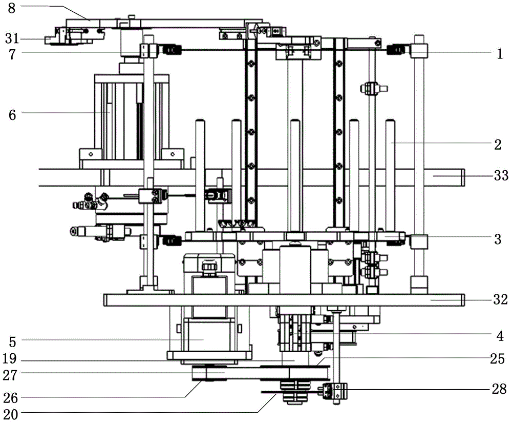
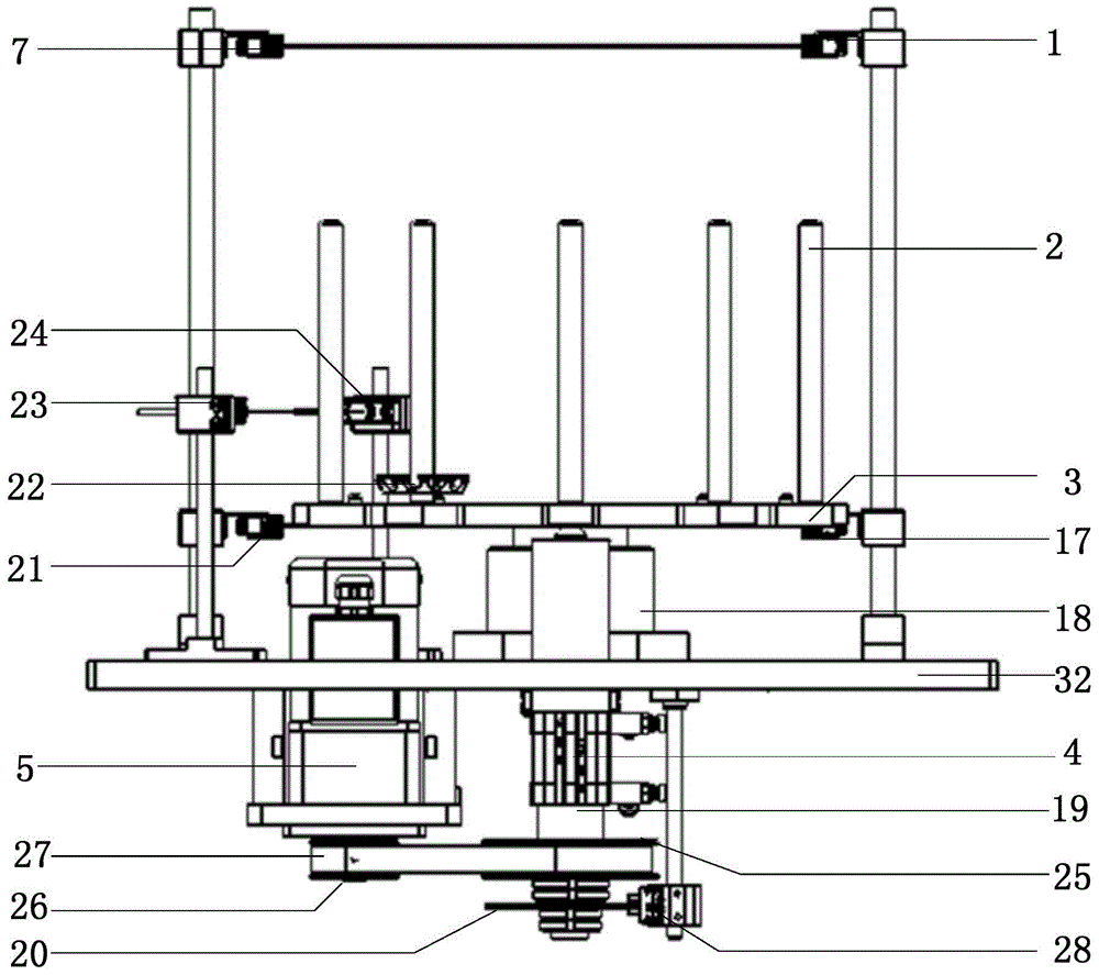
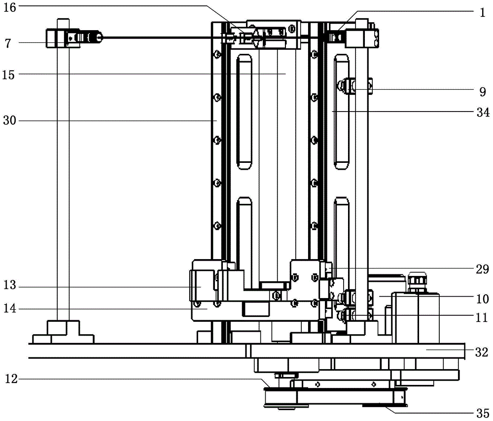
[0020] The cage automatic feeding device of the present invention mainly includes a platform, a feeding mechanism, a jacking mechanism and a pick-and-place mechanism, and the platform is provided with a lower platform 32 and an upper platform 33 (see figure 1 ), the feeding mechanism and the jacking mechanism are all installed on the lower platen 32, and the pick-and-place mechanism is installed on the upper platen 33. The feeding mechanism is located in front of the jacking mechanism, and the pick-and-place mechanism is located on the upper side of the jacking mechanism.

[0021] Such as figure 1 and figure 2 As shown, the feeding mechanism includes a feeding turntable 3, a rotating shaft 19 and a rotating mechanism. There are many (ten in the figure) central rods 2 evenly distributed on the feeding turntable 3, and the central rods 2 are used to insert the material column filled with the cage 22. The feeding turntable 3 is installed on the rotating shaft 19, and the rota...


PUM


Abstract

An automatic feeder of retainers comprises a feeding mechanism, a lifting mechanism and a pick-and-place mechanism which are mounted on a support. The feeding mechanism comprises a feeding turnplate, a rotating shaft and a rotating mechanism; hollow rods are evenly distributed on the feeding turnplate; the feeding turnplate is mounted on the rotating shaft; the rotating shaft is mounted on a rack; the rotating shaft is connected with the rotating mechanism. The lifting mechanism comprises a supporting base, a lifting plate, a finger cylinder and a lifting plate lift; a lifting guide rail is disposed on the supporting base; the lifting plate is mounted on the lifting guide rail through a sliding plate; the finger cylinder is disposed on the supporting base; the lifting plate lift is mounted on the supporting base and is connected with the sliding plate. The pick-and-place mechanism comprises a rocking cylinder, a feeding rotating arm and a pick-and-place claw; the pick-and-place claw is mounted on the feeding rotating arm; the feeding rotating arm is connected to a piston of the rocking cylinder; the rocking cylinder is mounted on the rack. The automatic feeder of the retainers has the advantages that automatic feeding of the retainers is achieved, the retainers can be transferred to a press-fitting station, work efficiency is improved, and assembly quality of hub units is guaranteed.

Description

technical field [0001] The invention relates to a device for automatic loading of a cage on an automobile wheel hub unit assembly line, and belongs to the technical field of wheel hub unit assembly. Background technique [0002] The hub unit plays a pivotal role in the automobile transmission system, and the cage is one of the key components of the hub bearing. Reliable and fast feeding of the cage is an important guarantee for the assembly quality of the hub unit. [0003] At present, during the assembly process of the hub unit, the cage is loaded manually. Not only is the loading speed slow and the labor intensity is high, but also it is easy to be inadvertent and miss assembly, and even cause misoperation, causing production accidents and other dangers. Contents of the invention [0004] Aiming at the problem of manual loading of the cage, the invention provides an automatic loading device for the cage with simple structure and convenient operation. [0005] The cage ...

Claims


Application Information

Patent Timeline
Patent Type & Authority Applications(China)
IPC IPC(8): B65G47/74
Inventor 丁昌伟王志民王晨曹小龙
Owner 济南易恒技术有限公司
Learn More