Method and device for measuring center point of pipeline end face

A center point and end face technology, which is applied in the field of measuring the center point of the pipeline end face, can solve the problems of affecting the accuracy of the geometric center, difficult to guarantee the measurement accuracy, and low measurement efficiency, and achieve strong contrast, fast measurement speed, and clearer edges of mark points. Effect

Active Publication Date: 2017-03-29
BEIJING INSTITUTE OF TECHNOLOGYGY
View PDF7 Cites 0 Cited by
  • Summary
  • Abstract
  • Description
  • Claims
  • Application Information

AI Technical Summary

Problems solved by technology

[0005] To sum up, no matter it is the traditional method or the currently widely used three-coordinate measuring machine, laser tracker, etc. for the measurement of pipeline endpoints, the common disadvantage is that too much reliance on human operation leads to low measurement efficiency. The position of the end point of the road cannot be directly measured. In engineering, the outer circle of the end face of the pipeline is usually measured first, and then the coordinates of the geometric center position are calculated. However, the measurement of the outer circle is affected by the quality of the image, making it difficult to guarantee the measurement accuracy, which affects the calculation. Accuracy of the resulting geometric center

Method used


Image

  • Method and device for measuring center point of pipeline end face
  • Method and device for measuring center point of pipeline end face
  • Method and device for measuring center point of pipeline end face

Examples


Embodiment 1

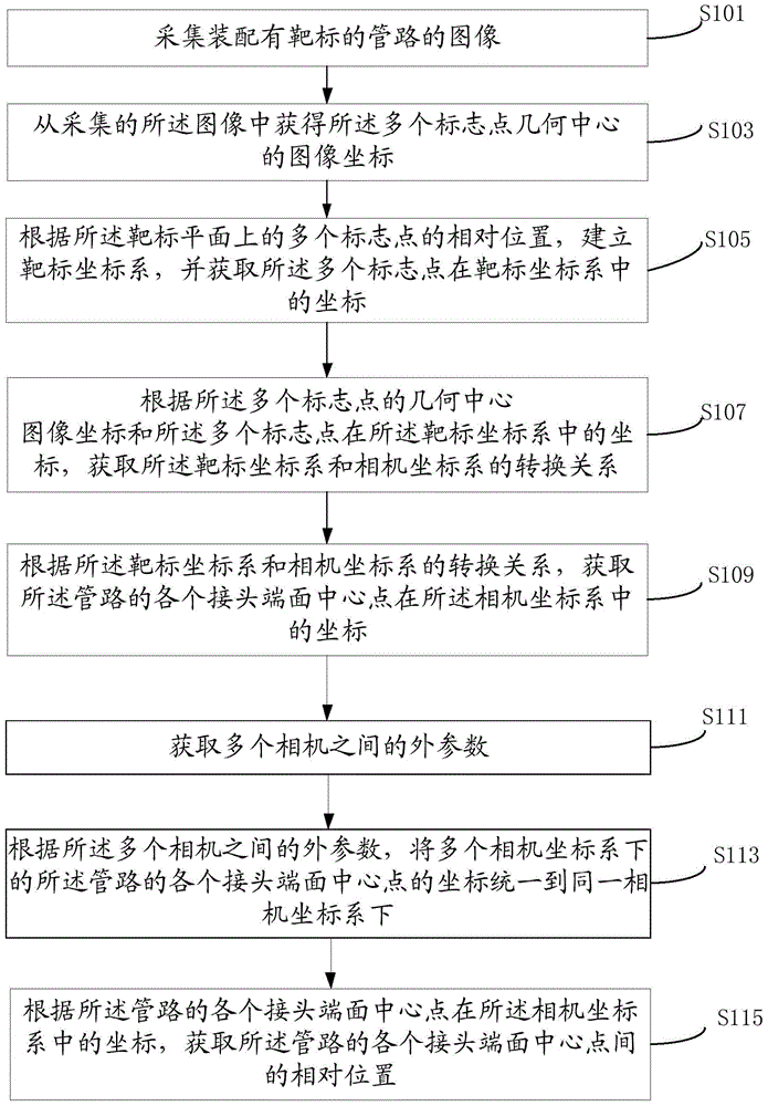
[0076] According to an aspect of the embodiments of the present invention, a method for measuring the center point of the end face of a pipeline is provided, such as figure 1 As shown, the method includes:

[0077] Step S101 , collecting an image of the pipeline equipped with the target.

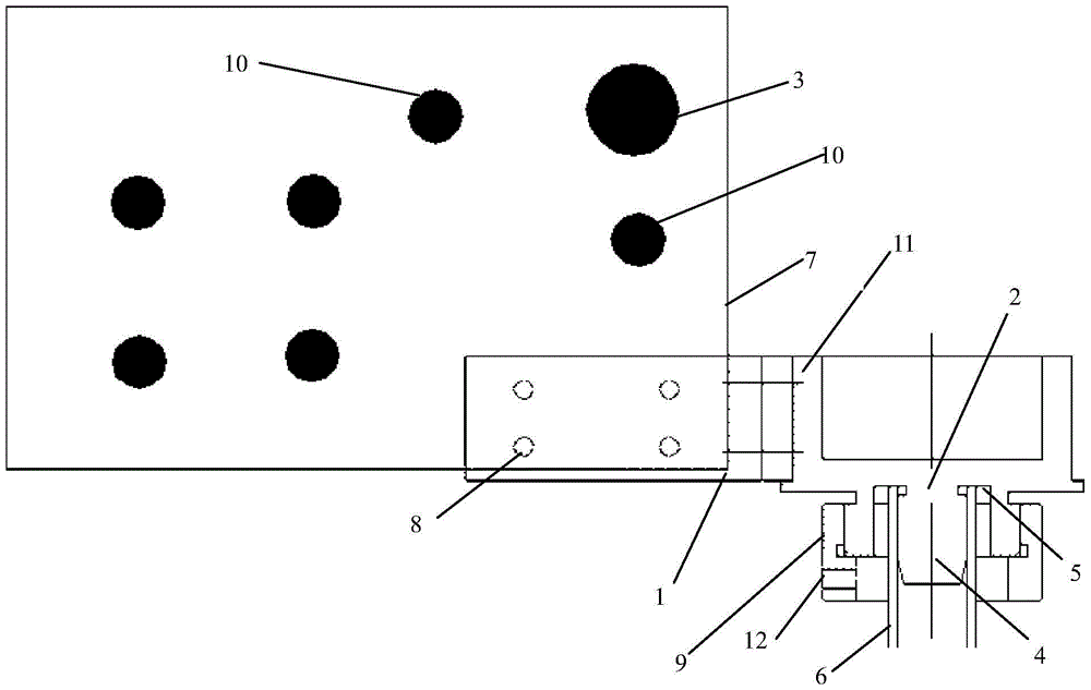
[0078] The target needs to be assembled to the pipe fitting before the end face center point of the pipe can be measured. like figure 2 As shown, the target plane 7 of the target is provided with a plurality of marking points, and the target plane can be plexiglass, and is fixed on the target through the fixing part 8 . The target plane 7 in the embodiment of the present invention is provided with seven marking points. Among them, the plurality of marking points include a large marking point 3 and a plurality of small marking points 10, the large marking point 3 is used to determine the origin of the target coordinate system, and the multiple small marking points 10 are used to determine...

Embodiment 2

[0114] According to another aspect of the present invention, a device 400 for measuring the center point of the end face of a pipeline is also provided, such as Figure 4 As shown, the device includes:

[0115] The image acquisition module 401 is used to acquire the image of the pipeline equipped with the target, and the target plane of the target is provided with a plurality of marking points;

[0116] an image coordinate obtaining module 403, configured to obtain the image coordinates of the geometric centers of the plurality of landmark points from the collected image;

[0117] A target coordinate system establishment module 405, configured to establish a target coordinate system according to the relative positions of the multiple marker points on the target plane, and obtain the coordinates of the multiple marker points in the target coordinate system;

[0118] The conversion relationship acquisition module 407 is configured to acquire the conversion relationship between ...


PUM


Abstract

The invention provides a method and device for measuring pipeline end face central points. The method includes the steps that an image of a pipeline with a target is collected; image coordinates of geometric centers of multiple mark points are acquired from the collected image; according to the relative positions of the mark points on a target plane, a target coordinate system is established, and coordinates of the mark points in the target coordinate system are acquired; according to the image coordinates of the geometric centers of the mark points and the coordinates of the mark points in the target coordinate system, the transformation relation between the target coordinate system and a camera coordinate system is acquired; according to the transformation relation between the target coordinate system and the camera coordinate system, coordinates of joint end face central points of the pipeline in the camera coordinate system are acquired; according to the coordinates of the joint end face central points of the pipeline in the camera coordinate system, the relative positions between the joint end face central points of the pipeline are acquired. By the adoption of the scheme, the speed and accuracy are high when the relative positions of the joint end face central points of the pipeline are measured.

Description

technical field [0001] The invention relates to the technical field of optical measurement, in particular to a method and device for measuring the center point of an end face of a pipeline. Background technique [0002] Pipelines are widely used in complex mechanical and electrical products in aviation, aerospace, special vehicles and other industrial fields. Whether they can be installed reliably or not directly affects product quality. At present, one of the most direct and effective means to ensure the quality of pipeline processing and to achieve stress-free assembly in engineering is still to obtain the direction of the intermediate conduit in the pipeline and the relative position of the endpoints of the pipeline through the physical inspection of the pipeline after welding. Coordinates, and accurate correction is made on this basis. [0003] In the prior art, the measurement of the position of the center point of the end face of the pipeline joint includes: tradition...

Claims


Application Information

Patent Timeline
Patent Type & Authority Patents(China)
IPC IPC(8): G01B11/00
Inventor 刘少丽金鹏刘检华丁晓宇王骁孙鹏王爱民
Owner BEIJING INSTITUTE OF TECHNOLOGYGY
Why Eureka
Try Eureka