
A film removal device

A film layer and driving unit technology, which is applied in the field of display device preparation, can solve the problems of decreased production efficiency, impact on exposure and development process, prolonged R&D cycle, etc.

Active Publication Date: 2016-01-20
BOE TECH GRP CO LTD
View PDF9 Cites 0 Cited by
  • Summary
  • Abstract
  • Description
  • Claims
  • Application Information

AI Technical Summary

Problems solved by technology

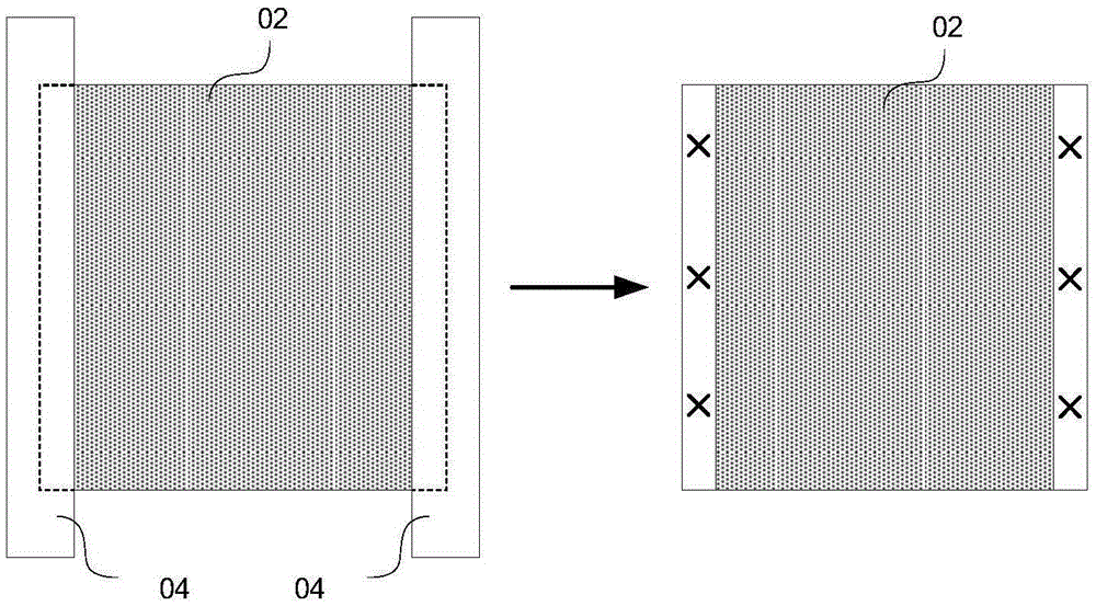
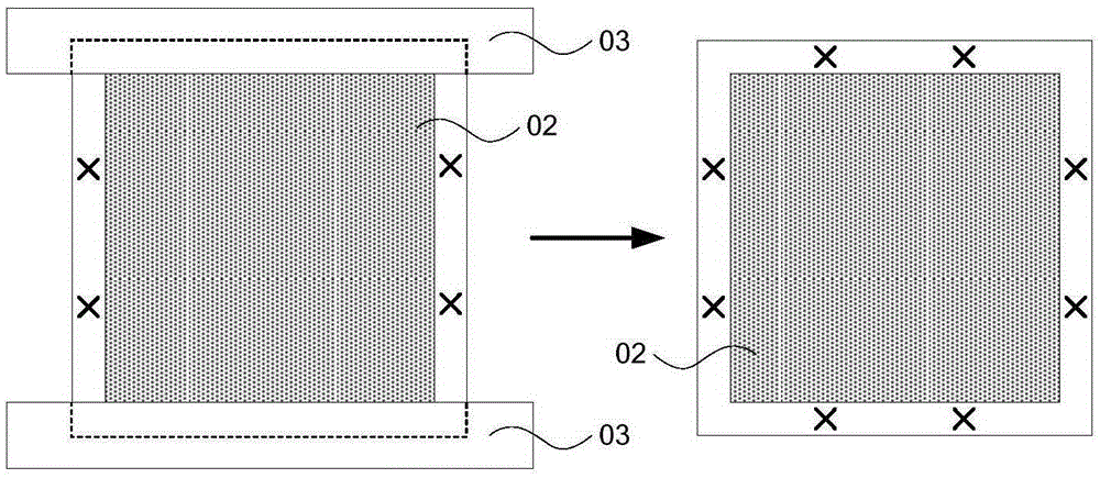
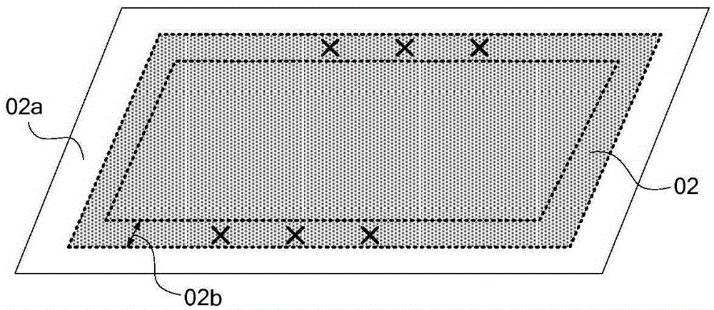
[0005] Yet, because the operating scope of the edge scraping machine that prior art provides is only limited to the two sides and / or all around of film layer, and the width scope of film layer scraping is limited, as figure 2 As shown, when the alignment mark X is located in the unconventional area 02b inside the film layer 02, it is difficult to remove the film layer 02 above the alignment mark X in the above-mentioned unconventional area 02b by using the edge scraper 03 of the prior art , because the film layer 02 above the alignment mark X is difficult to remove, that is, the alignment mark X is difficult to expose, resulting in poor alignment and affecting the subsequent exposure and development process. Therefore, in this case, it can only be manually removed. The film layer on the registration mark in the non-standard area, resulting in a decrease in production efficiency; if the film layer on the registration mark in the non-conventional area is not scraped, a new film layer must be re-developed that must be transparent to infrared light materials, and further, it is necessary to upgrade the alignment system of the exposure machine and increase the recognition system for infrared light, resulting in prolonged R&D cycles and increased production costs

Method used


Image

  • A film removal device
  • A film removal device
  • A film removal device

Examples


Embodiment Construction

[0030] The following will clearly and completely describe the technical solutions in the embodiments of the present invention with reference to the accompanying drawings in the embodiments of the present invention. Obviously, the described embodiments are only some, not all, embodiments of the present invention. Based on the embodiments of the present invention, all other embodiments obtained by persons of ordinary skill in the art without making creative efforts belong to the protection scope of the present invention.

[0031] The embodiment of the present invention provides a film layer removal device 01, such as image 3 As shown, the film removal device 01 includes: a removal unit 10 ; a drive unit 20 for driving the removal unit 10 to move; and a control unit 30 for controlling the drive unit 20 .

[0032] Among them, such as Figure 4 As shown, the removal unit 10 includes: a cavity 11; the cavity 11 includes an opening area 110; a rotatable removal body 12 arranged in ...


PUM


Abstract

The embodiment of the invention provides a film removal device, and relates to the field of preparation of display devices. Precise removal of any area of a film can be realized; different requirements in process production can be met; the cost can be lowered, and the production efficiency can be improved. The film removal device comprises a removal unit, a drive unit for driving the removal unit to move and a control unit which controls the drive unit, wherein the removal unit comprises a cavity; the cavity comprises an open area, a rotatable removal body, an injection pipe and an air pumping assembly, wherein the rotatable removal body is arranged in the open area of the cavity and is parallel to the surface of the film; the injection tube is arranged in the cavity and injects a removal liquid into the removal body; the air pumping assembly is arranged in the cavity; an air pumping pipe of the air pumping assembly points to the removal body. The invention is used for the preparation of the film removal device which can realize the precise removal of any area of the film.

Description

technical field [0001] The invention relates to the field of preparation of display devices, in particular to a film layer removing device. Background technique [0002] In the manufacturing process of display devices, a film layer with a predetermined pattern is often formed through a patterning process. The patterning process is mainly to expose and develop the photoresist coated on the film layer to obtain a photoresist layer with a specific pattern, and to etch the exposed film layer of the photoresist layer, so that the film layer forms a predetermined pattern. pattern. [0003] Since the exposure of the photoresist layer needs to be accurately aligned with the mask plate, before exposing the photoresist layer, it is necessary to pre-set a plurality of alignment elements with different distribution positions on the substrate formed with the film layer. Mark (workmark), because the current exposure machine recognizes the alignment mark through visible light, and most o...

Claims


Application Information

Patent Timeline
Patent Type & Authority Patents(China)
IPC IPC(8): G03F9/00
Inventor 谷耀辉舒适张锋
Owner BOE TECH GRP CO LTD
Learn More