Low profile ultra wide band antenna array setting method

An ultra-wideband antenna and low-profile technology, which is applied in antenna arrays, antenna grounding devices, antennas, etc., to solve the problem of resonance points and eliminate the effect of strong mutual coupling

Inactive Publication Date: 2015-01-28
SOUTHWEST CHINA RES INST OF ELECTRONICS EQUIP
View PDF3 Cites 14 Cited by
  • Summary
  • Abstract
  • Description
  • Claims
  • Application Information

AI Technical Summary

Problems solved by technology

[0009] The technical problem to be solved by the present invention is: aiming at the deficiencies in the design of the existing ultra-wideband low-profile array, the present invention proposes a method for setting up a low-profile ultra-wideband antenna array, which eliminates the problem of using slot line antenna elements to form an array by adopting the method of manufacturing mirror images. Due to the inherent resonance problem, the array unit is designed based on the strong mutual coupling effect, and finally the parasitic unit is used to adjust the working bandwidth of the array

Method used


Image

  • Low profile ultra wide band antenna array setting method
  • Low profile ultra wide band antenna array setting method
  • Low profile ultra wide band antenna array setting method

Examples


Embodiment 1

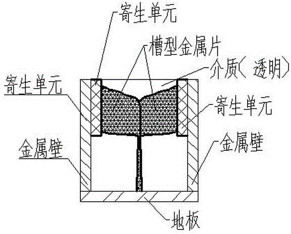
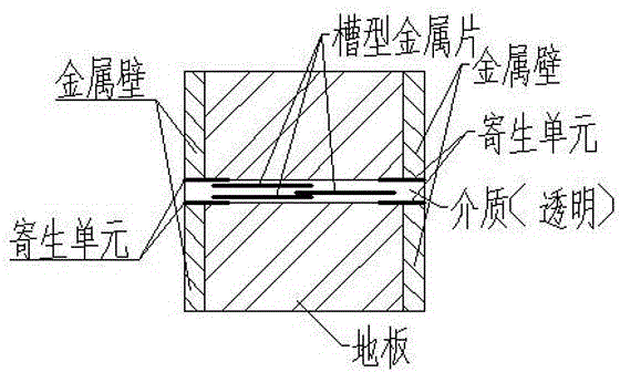
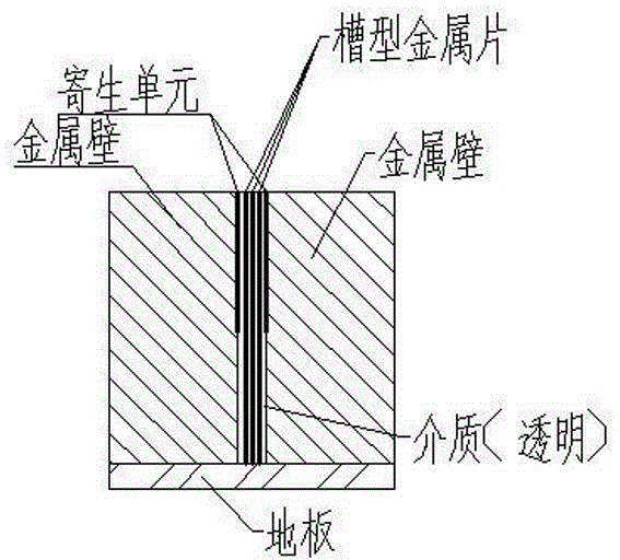
[0039] Taking a classic BAVA array unit as an example, before its structure is improved, the initial bandwidth is not wide, and there is an obvious resonance at 8GHz. In order to solve this problem, a metal wall is added between the units during design. After adding the metal wall, due to the existence of the mirror image of the radiating unit, the resonance point is eliminated, and the array bandwidth is greatly expanded. Next, the strong mutual coupling array design method is adopted, and by adjusting the capacitive impedance of the array unit, no resonance in the 1.9GHz-18GHz frequency band is realized, and the section height of the entire array unit can be controlled below 15mm. The process of widening the bandwidth of BAVA array with structure improvement is more clear on the Smith chart. Figure 2a is the initial state, Figure 2b After introducing mirroring and Figure 2c In order to adjust the Smith chart of the three-state array after mutual coupling, it can be se...


PUM


Abstract

The invention relates to the technical field of antennas, in particular to a low profile ultra wide band antenna array setting method which overcomes the shortcoming in ultra wide band array design. A low profile ultra wide band design method is provided. An image making mode is adopted to solve the resonance problem caused by the fact that slot antenna units are adopted to form the array, then design is conducted on the array units based on the high cross coupling effect, and finally a parasitic element is adopted to adjust the working band width of the array. The method achieves antenna low profile ultra wide band characteristics and has good manufacturability and assembly capability. A metal wall image making mode is arranged between a BAVA antenna medium and a BAVA antenna floor, meanwhile the directional diagram product theorem and the electromagnetic period boundary theory are utilized to remove mutual coupling of the array units and achieve the aim of increasing band width.

Description

technical field [0001] The invention relates to the technical field of antennas, in particular to a method for arranging a low-profile ultra-wideband antenna array. Background technique [0002] Antennas are divided into resonant antennas (standing wave antenna, fixed frequency band) and non-resonant antennas (traveling wave antenna, wide frequency band). Traveling wave antennas are divided into four categories according to the formation principle: long antenna and loading, resonant traveling wave array, slow wave, and leaky wave. [0003] ETSA tapered slot antennas are Vivaldi antennas, LTSA antennas, CWSA antennas or BWSA antennas. [0004] The VIvaldi antenna is a kind of TSA antenna, which is an antenna with an exponential gradient line, and the other is an LTSA antenna. These two antennas together form a TSA antenna. The TSA antenna usually uses a microstrip line for feeding, and the microstrip line is an asymmetric transmission line, and the transmitting end of the T...

Claims


Application Information

Patent Timeline
Patent Type & Authority Applications(China)
IPC IPC(8): H01Q1/52H01Q1/38H01Q1/48H01Q21/00
Inventor 张波
Owner SOUTHWEST CHINA RES INST OF ELECTRONICS EQUIP
Why Eureka
Try Eureka