eye tracker lighting

An eye-tracking and eye-based technology, used in eye-testing equipment, acquisition/recognition of eyes, instruments, etc., can solve the problems of expensive, bulky lenses, etc., and achieve the effect of high conversion efficiency, large diffusion aperture, and compact form factor

Active Publication Date: 2017-09-05
TOBII TECH AB
View PDF3 Cites 0 Cited by
  • Summary
  • Abstract
  • Description
  • Claims
  • Application Information

AI Technical Summary

Problems solved by technology

Therefore, for efficient coupling, large numerical aperture lenses are required, i.e. high transmission, which in turn shows that the lenses are bulky and expensive

Method used


Image

  • eye tracker lighting
  • eye tracker lighting
  • eye tracker lighting

Examples


Embodiment Construction

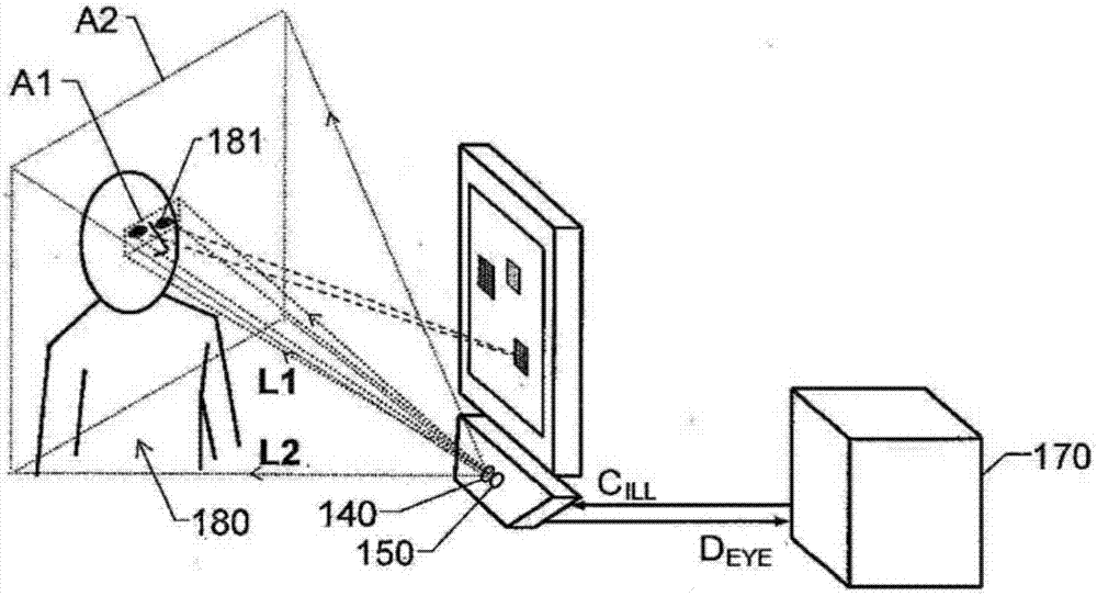
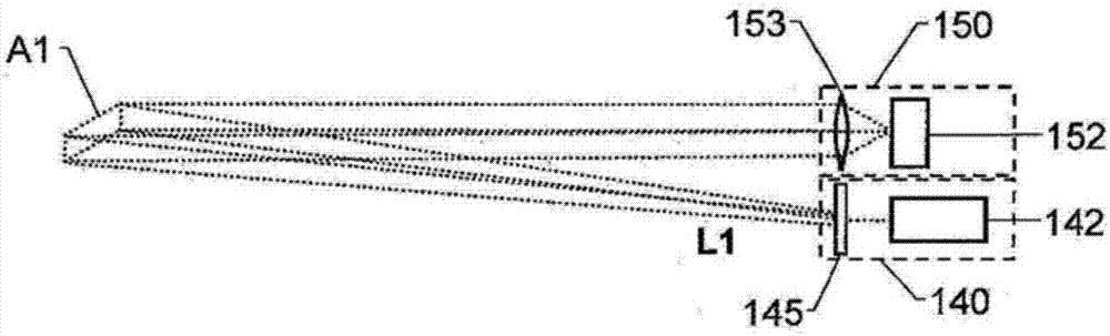
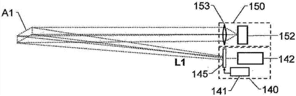
[0036] The present invention relates to the tracking of a subject's eyes or gaze. Naturally, this does not exclude facial features, facial expressions and / or gestures of additional subjects beyond that to be tracked and / or analyzed. In this context, the invention addresses the specific problem of directing the light rays needed to achieve a sufficiently high image contrast towards the object while minimizing the amount of excess light. The proposed device can also provide homogenous illumination covering a relatively large area of ​​an object. In general, this is achieved by shaping the beam so that the area onto which the light is cast matches the field of view of the image sensor / camera used to register the image data representing the relevant part of the object.

[0037] Of course, the lighting setup becomes more energy efficient if only the most relevant part of the camera's field of view is illuminated, eg estimating where the subject's eyes will be located, and if the l...


PUM


Abstract

An illuminated object (180) with movement of at least one eye of the illuminated object registered by an eye tracker for generating result data (DEYE). To achieve the above object, a coherent light source in the light generating means (140) generates at least one well-defined light beam (L1, L2). A diffractive optical element is arranged between the interference light source and the output of the light generating means (140). The diffractive optical element is used to direct the light beam (L1) towards at least a first designated area (A1), which is estimated to cover at least one eye of the subject (180). Image registration means (150) registers light from at least one light beam (L1, L2) that has been reflected to the object (180). Result data (DEYE) is generated in response to these light reflections, wherein the result data (DEYE) represents movement of at least one eye of the subject (180).

Description

technical field [0001] The present invention relates to illuminating a subject, the movement of at least one eye of said subject being registered by an eye tracker for generating resulting data (ie information about eye and / or gaze position). In turn, this data can be used to control computer means, or be specifically registered for analysis purposes (eg in conjunction with psychology or in diagnosing various medical conditions). Precise information on the position of each eye of the viewer is necessary for autostereoscopic displays to ensure that the correct image is presented and projected to each eye in order to create an immersive three-dimensional effect. In more detail, the invention relates to a device according to the preamble of claim 1 . Background technique [0002] The prior art includes directional optical illuminators for eye trackers. Such illuminators are beneficial over static reproductions because at each point in time they only illuminate a small portion...

Claims


Application Information

Patent Timeline
Patent Type & Authority Patents(China)
IPC IPC(8): G02B27/09A61B3/10A61B3/113G02B26/08G02B27/00G06F3/01
CPCA61B3/113G02B5/18G02B27/0093G06F3/013G06V40/19
Inventor 理查德·海因兹尔马蒂亚斯·库尔德克普彼得·布利克斯特马滕·斯科苟
Owner TOBII TECH AB
Why Eureka
Try Eureka