Fish tank heating rod structure

A technology of heating rods and fish tanks, applied in fish farming, application, animal husbandry, etc., can solve the problems of easy heating, large heating area, etc., and achieve the effect of easy heating, large heating area, and fast heating

Inactive Publication Date: 2015-02-04
李伟
View PDF9 Cites 0 Cited by
  • Summary
  • Abstract
  • Description
  • Claims
  • Application Information

AI Technical Summary

Problems solved by technology

[0005] In view of the above defects, the present invention provides a fish tank heating rod structure wit

Method used


Image

  • Fish tank heating rod structure
  • Fish tank heating rod structure
  • Fish tank heating rod structure

Examples


Embodiment 1

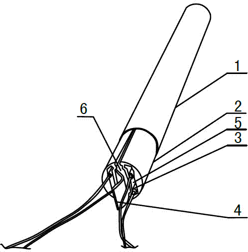
[0025] Such as Figure 1-4 As shown, the fish tank heating rod structure described in the embodiment of the present invention includes a heating tube 1 and two heating fins 2, the heating tube 1 is a hollow cylindrical structure and one or both of the bottom surfaces are set as open ends, The inside of the heating tube 1 is provided with two heating sheets 2 with a semicircular longitudinal section, and there is a clamping groove 6 between the two heating sheets 2, and a spring piece 4 is fixedly inserted inside the clamping groove 6, and the spring piece 4 is composed of several arc-shaped surfaces, thus forming a wavy surface structure;

[0026] Correspondingly, the protrusions on both sides of the outer surface of the spring piece 4 press against the inner side of the heating piece 2 respectively, thereby pushing each piece of heating piece 2 to the inner wall surface of the heating tube 1, so that the heating piece 2 can support and bounce off more Close to the tube wall ...

Embodiment 2

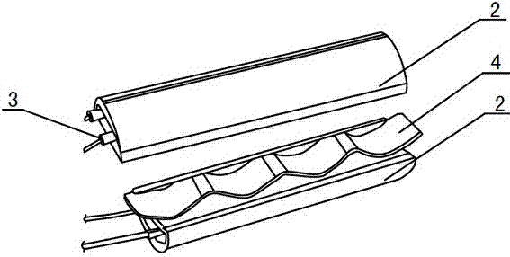
[0028] Such as Figure 1-4 As shown, the fish tank heating rod structure described in the embodiment of the present invention includes a heating tube 1 and two heating fins 2, the heating tube 1 is a hollow cylindrical structure and one or both of the bottom surfaces are set as open ends, Two heating sheets 2 are arranged inside the heating tube 1, and a spring sheet 4 is inserted between the two heating sheets 2;

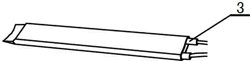
[0029] The protrusions on both sides of the outer surface of the spring sheet 4 press against the inner side of the heating sheet 2 respectively, thereby pushing each heating sheet 2 to the inner wall surface of the heating tube 1, so that the heating sheet 2 can be supported and bounced closer to the heating tube 1 to achieve the effects of large heating area, easy heating, and fast heating; at the same time, each heating sheet 2 is provided with a heating rod 3 inside.

Embodiment 3

[0031] Such as Figure 1-4 As shown, the fish tank heating rod structure described in the embodiment of the present invention includes a heating tube 1 and two heating fins 2, two heating fins 2 are arranged inside the heating tube 1, and there is a clip between the two heating fins 2. Groove 6 and a spring piece 4 is fixedly inserted inside the clamping groove 6, and the spring piece 4 is a wavy curved surface structure;

[0032] Correspondingly, both sides of the outer surface of the spring sheet 4 press against the inner side of the heating sheet 2 respectively, thereby pushing each heating sheet 2 to the inner wall surface of the heating tube 1, so that the heating sheet 2 can be supported and bounced closer to the heating tube 1 the tube wall.


PUM


Abstract

The invention relates to a fish tank heating rod structure, which comprises a heating tube and two heating sheets, wherein the two heating sheets are arranged inside the heating tube, a clamp groove is formed between the two heating sheets, in addition, a leaf spring is fixedly inserted inside the clamp groove and consists of a plurality of arc-shaped surfaces, and the two sides of the outer surface of the leaf spring are respectively and tightly propped against the inner sides of the heating sheets, so each heating sheet is pushed to the inner wall surface of the heating tube, the inside of each heating sheet is provided with a gap, and in addition, a heating rod is placed inside each gap. The fish tank heating rod structure has the beneficial effects that one spring is clamped between the two heating sheets, and through the tension of the spring, the heating sheets can be supported and propped open, and can be closer to the tube wall of the heating tube, so no cavity is formed between the outer heating tube and the inner heating sheets; the fish tank heating rod structure has the advantages that the heated area is large, the heated effect can be easily achieved, the heating speed is high, and the like; one gap is formed in the middle part of each heating sheet and is used for containing the corresponding heating rod.

Description

Technical field [0001] The present invention involves a heating rod, especially for a fish tank heating rod structure. Background technique [0002] At present, there are two main structures of the heating rods on the market. One is to use dual metal sheet to control the temperature and place a dual metal piece in the interior of the heating rod. The two sides of the dual metal tablets are different materials. The heating and expansion coefficient is different.Using this point can be automatically disconnected at the set temperature; the second is to use thermal resistance detection temperature, and use thyristor and other to control the interruption of heating rods.The thermistor and heating rod are integrated, and the advantage is that installation is more convenient. [0003] Ordinary heating sticks are generally changed in two years, because the internal dual metal tablets have been used for a long time, and faults are prone to occur.Generally, the heating rod of the glass is...

Claims


Application Information

Patent Timeline
IPC IPC(8): A01K63/06
CPCA01K63/065
Inventor 李伟
Owner 李伟
Why Eureka
Try Eureka