Light guide plate transfer molding method, light guide plate, and planar light source apparatus
A technology of light guide plate and transfer printing surface, applied in the direction of light source, electric light source, point light source, etc., can solve the problems of brightness drop, large leakage, uneven brightness, etc., and achieve the effect that the brightness is not easy to drop
- Summary
- Abstract
- Description
- Claims
- Application Information
AI Technical Summary
Problems solved by technology
Method used
Image
Examples
Embodiment approach 1
[0129] Hereinafter, only the part corresponding to one light source 32 ( Figure 4 or Figure 5 However, any of the surface light source devices described below are used as the surface light source devices 21 and 22 by arranging a plurality of light sources 32 .
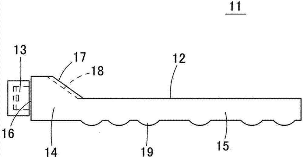
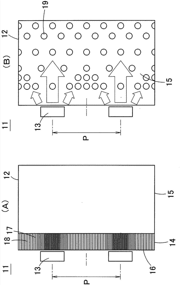
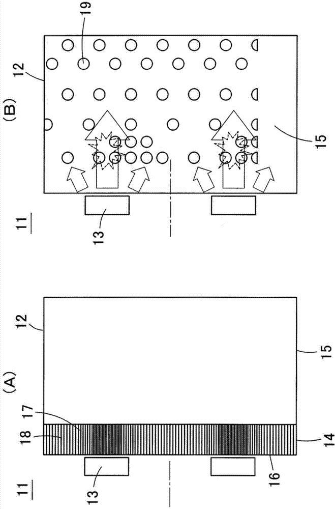
[0130] Figure 7 (A) and Figure 7 (B) is a perspective view showing the top and bottom of the surface light source device 31 according to Embodiment 1 of the present invention. Figure 8 is a schematic cross-sectional view of the surface light source device 31 in a direction perpendicular to the light incident surface 38 . Figure 7 The diagram of the surface light source device 31 shown is only to show Figure 5 (A) and Figure 5 The part corresponding to one light source 32 in the surface light source device 22 shown in (B) ( Figure 4 or Figure 5 A distance between the boundary lines B) (a part of the original surface light source devices 21, 22).
[0131] The surface light source device 31 is composed o...
Embodiment approach 2
[0180] Figure 22 (A) and Figure 22 (B) is a perspective view from the top side and a perspective view from the bottom side showing the surface light source device 50 according to Embodiment 2 of the present invention. In this surface light source device 50 , the directivity conversion patterns 36 are radially provided on the inclined surface 37 . Regarding other configurations, since they are the same as in Embodiment 1, explanations will be omitted by attaching the same symbols to the same components as in Embodiment (the same applies to the following embodiments).
[0181] In this embodiment, when viewed from a direction perpendicular to the upper surface of the light guide plate 33, the direction of the directivity conversion pattern 36 is approximately parallel to the radiation direction of the light from the light source 32, so when a point light source is used, the direction of the light from the inclined surface is prevented. 37's light leak effect is further improv...
Embodiment approach 3
[0183] Figure 23 (A) and Figure 23 (B) is a perspective view from the top side and a perspective view from the bottom side showing the surface light source device 51 according to Embodiment 3 of the present invention. In the surface light source device 51 according to Embodiment 2, the protrusion 52 having a shape approximately half of the truncated cone shape protrudes from the upper surface of the light introduction portion 35 so as to overlap the inclined surface 37 . Such as Figure 24 As shown, the outer peripheral surface of the protrusion 52 becomes an inclined surface 53 inclined from the upper surface of the protrusion 52 to the light emitting surface 39 of the light guide plate main body 34, and a plurality of directivity conversion patterns 36 in a V-shaped groove structure are formed on the inclined surface 53. . When viewed from a direction perpendicular to the light exit surface 39, the directivity conversion pattern 36 becomes an arc-shaped band-shaped regi...
PUM
| Property | Measurement | Unit |
|---|---|---|
| Glass transition temperature | aaaaa | aaaaa |
| Melting point | aaaaa | aaaaa |
Abstract
Description
Claims
Application Information
 - R&D
- Intellectual Property
- Life Sciences
- Materials
- Tech Scout
- Unparalleled Data Quality
- Higher Quality Content
- 60% Fewer Hallucinations
Browse by: Latest US Patents, China's latest patents, Technical Efficacy Thesaurus, Application Domain, Technology Topic, Popular Technical Reports.
© 2025 PatSnap. All rights reserved.Legal|Privacy policy|Modern Slavery Act Transparency Statement|Sitemap|About US| Contact US: help@patsnap.com


