
Speed regulating mechanism for trowelling plate of electric trowelling machine

A technology of speed regulating mechanism and troweling machine, which is applied in the direction of building structure, construction, and building material processing, etc., which can solve the problems of low efficiency and cumbersome operation process, and achieve the effect of convenient operation, low cost and simple structure

Active Publication Date: 2015-02-04
MASALTA ENG HEFEI
View PDF6 Cites 0 Cited by
  • Summary
  • Abstract
  • Description
  • Claims
  • Application Information

AI Technical Summary

Problems solved by technology

The operation process is cumbersome and the efficiency is very low

Method used


Image

  • Speed regulating mechanism for trowelling plate of electric trowelling machine
  • Speed regulating mechanism for trowelling plate of electric trowelling machine
  • Speed regulating mechanism for trowelling plate of electric trowelling machine

Examples


Embodiment Construction

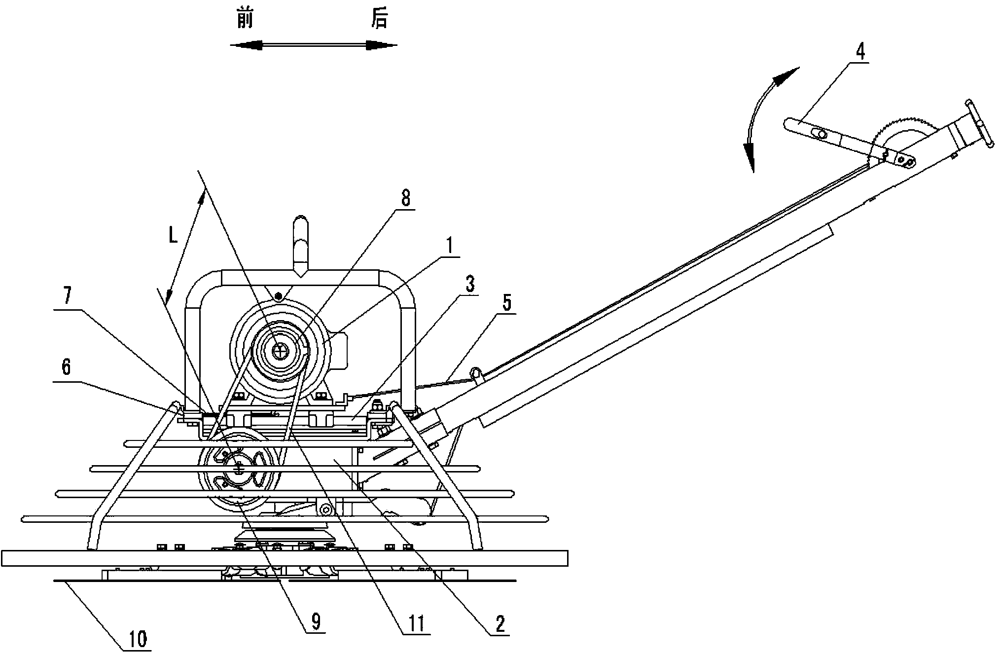
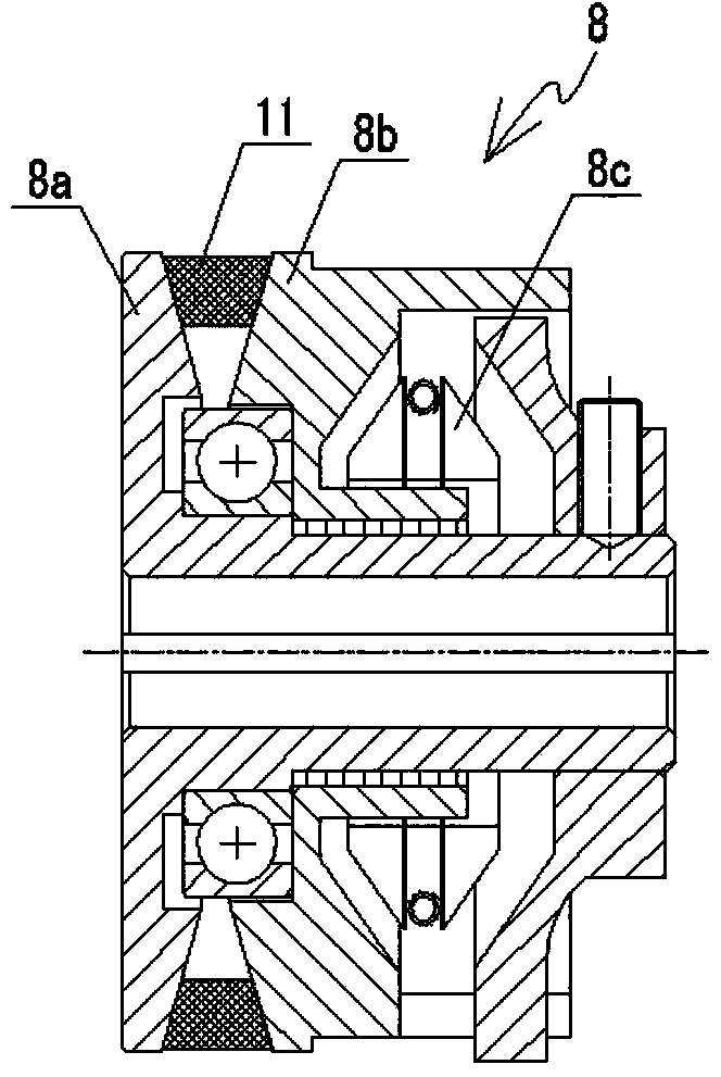
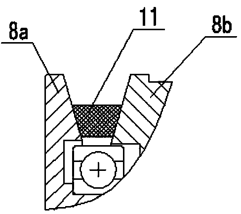
[0019] see figure 1 , figure 2 and Figure 2a , the structural form of the speed regulating mechanism of the electric troweling machine in this embodiment is: in the speed regulating device, the rotation output of the drive motor 1 is driven by the belt transmission structure, and then decelerated by the speed reducer 2 with a fixed reduction ratio. Finally, the wiper 10 is driven to rotate by the output shaft of the reducer, and the adjustment of the wiper 10 is realized by adjusting the effective diameter of the driving pulley 8a in the belt transmission structure arranged between the motor 1 and the reducer 2 using the speed control handle 4. The belt transmission structure is composed of a driving pulley 8a fixedly arranged at the output shaft end of the motor 1, a driven pulley 9 fixedly arranged at the output shaft end of the speed reducer 2, and a transmission belt 11.

[0020] Such as figure 1 As shown, in this embodiment, a longitudinal guide rail 3 is fixedly arr...


PUM


Abstract

The invention discloses a speed regulating mechanism for a trowelling plate of an electric trowelling machine. The speed regulating mechanism is characterized in that rotation output of a driving motor is driven by a belt driving structure and then decelerated by a speed reducer with a fixed speed reduction ratio in a speed regulating device; an output shaft of the speed reducer drives the trowelling plate to rotate; the speed of the trowelling plate is regulated by regulating the size of the effective diameter of a driving belt wheel in the belt driving structure between the motor and the speed reducer; the belt driving structure comprises the driving belt wheel fixedly arranged at the end of the output shaft of the motor, a driven belt wheel fixedly arranged at the end of the output shaft of the speed reducer and a transmission belt. The speed regulating mechanism for the trowelling plate of the electric trowelling machine is simple in structure, stable in performance, convenient to operate and low in cost.

Description

technical field [0001] The invention relates to a trowel speed regulating mechanism used in a small construction machinery electric trowel. Background technique [0002] In the prior art, there are usually two methods for adjusting the rotating speed of the electric trowel: [0003] One is to use variable frequency motor to adjust the speed. Although this form can realize variable speed, the structure of the variable frequency motor is complex, expensive, the cost of the machine is too high, and the product competitiveness is low. [0004] The second is that the driving wheel and the driven wheel are designed with two different wheel diameters, that is, the large-sized driving wheel and the small-sized driven wheel form a high-speed output stage, and the small-sized driving wheel and a large-sized driven wheel form a low-speed output stage; this form has a sluggish structure , the belt must be manually adjusted from high speed to low speed or from low speed to high speed in...

Claims


Application Information

Patent Timeline
IPC IPC(8): E04G21/10
Inventor 胡宏王振晋毓望
Owner MASALTA ENG HEFEI
Learn More