Water flow power generating device

A water flow power generation and generator technology, which is applied in the field of water flow power generation devices and hydroelectric power generation devices, can solve problems such as low power generation efficiency, and achieve the effects of avoiding radial loss of water flow, improving efficiency, and reducing maintenance time

Active Publication Date: 2015-02-04
王承辉 +1
View PDF5 Cites 17 Cited by
  • Summary
  • Abstract
  • Description
  • Claims
  • Application Information

AI Technical Summary

Problems solved by technology

In recent years, the exploration and development of hydroelectric power generation technology is in the ascendant. It can be seen from the published information that the power generation device that uses the kinetic energy of the horizontal flow of water to generate electricity basically uses a rotating body in the water, and uses the rotating body in the natural water flow. Under the influence of rotation to generate electricity, the structure can be roughly divided into two types, one is a power generation device whose rotation axis is parallel to the horizontal plane, and the other is a power generation device whose rotation axis is perpendicular to the horizontal plane. Due to its own weight, a large flow of water flow energy is required to start power generation, so the power generation efficiency of these water flow power generation devices is not high

Method used


Image

  • Water flow power generating device
  • Water flow power generating device
  • Water flow power generating device

Examples


Embodiment Construction

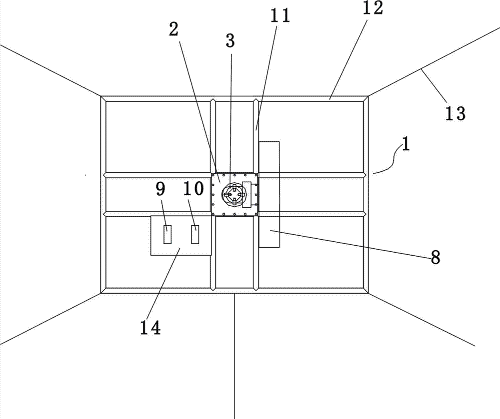
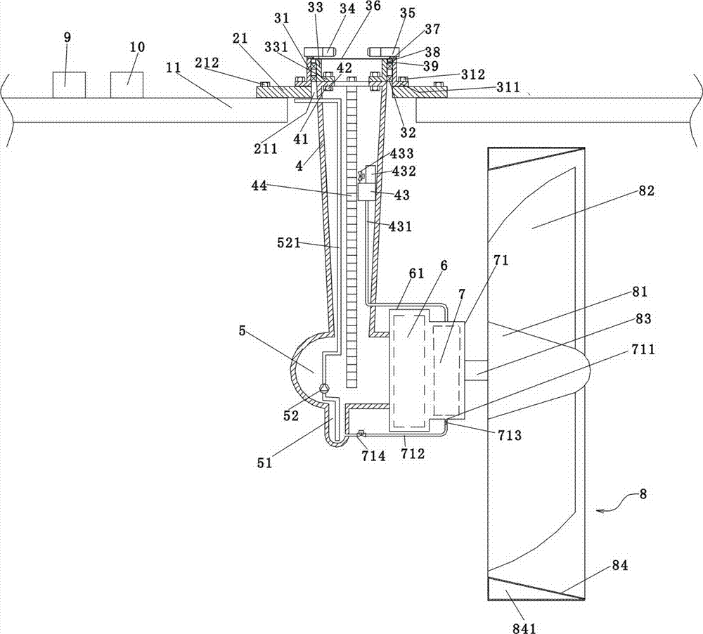
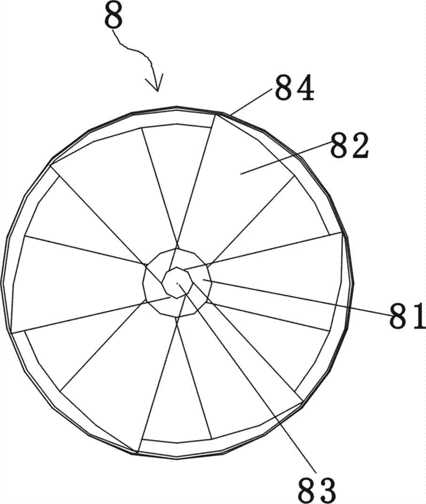
[0030] Such as figure 1 , 2 , 3, the water flow power generation device of the present invention includes a suspension frame 1, an installation platform 2, a rotating mechanism 3, a tower tube 4, a cabin 5, a generator 6, a gear box 7, an impeller 8, a control room 9 and a transformer 10;

[0031] The suspension frame 1 includes a "well" frame formed by welding several built-in buoys 11 and a square frame surrounded by several external buoys 12. One end of the center of the "well" frame is fixed on the side wall of the external buoy, and each of the four corners of the square frame is connected with a set of pull ropes 13 and ground anchors, and the ground anchors are placed on the underwater ground to make the frame fixed and float on the water surface superior;

[0032] The installation platform 2 is a square metal plate 21, and the center of the metal plate is provided with a round hole 211 for the upper end of the tower to pass through, and the outer edge of the metal p...


PUM


Abstract

The invention provides a water flow power generating device, which comprises an installing platform, a rotating mechanism, a tower tube, a machine cabin, a power generator, a gearbox and an impeller, wherein the installing platform is positioned on the water surface, the rotating mechanism is arranged on the installing platform, the tower tube, the machine cabin, the power generator, the gearbox and the impeller are positioned in the water, the upper end part of the tower tube is fixedly arranged on the rotating mechanism, the power generator and the gearbox are arranged at one side of the machine cabin, the impeller consists of a wheel hub and a plurality of blades, a center shaft of the wheel hub is connected with the power generator through the gearbox, the telecentric ends, far away from the center of the wheel hub, of the blades are provided with a wheel ring in a sleeving way, the wheel ring is of a cylindrical structure with the hollow side wall, and through the hollow structure of the wheel ring, the buoyancy obtained by the impeller in water counteracts the self weight of the impeller, so the impeller becomes a zero-weight impeller, the installing platform is fixedly arranged on a suspension framework consisting of a floating tube, and the suspension framework is fixed and floats on the water surface through pull ropes and ground anchors. The water flow power generating device has the advantages that the impeller can fast rotate under the water flow impact without overcoming the self weight, and the work obtained through the fast rotation is completely converted into the power generating power, so the power generating efficiency is greatly improved.

Description

technical field [0001] The present invention relates to a power generation device, in particular to a hydroelectric power generation device, and more particularly to a water flow power generation device which utilizes the kinetic energy of horizontal flow of tidal water, ocean current or river water to generate electricity. Background technique [0002] The power generation using natural energy includes wind power generation and hydropower generation. Generally, hydropower generation is to build dams in rivers, raise the water level, and use the potential energy of water to drive water turbines to generate electricity. This kind of hydropower generation uses the potential energy formed by the vertical drop of water flow to generate electricity. Power generation must have a certain water level difference, so the setting conditions are limited. China has vast sea areas and inland river basins. The water in the rivers and seas flows continuously all the time. These water fl...

Claims


Application Information

Patent Timeline
Patent Type & Authority Applications(China)
IPC IPC(8): F03B13/00F03B13/26F03B3/12F03B11/00
CPCF03B3/12F03B11/00F03B13/10F03B15/00F05B2240/93Y02E10/20
Inventor 王承辉王世全王世一
Owner 王承辉
Why Eureka
Try Eureka